


Dodge Engineering & Controls, Inc.
Toll Free (877) 334-2875 Fax: (978) 244-1422
Installation
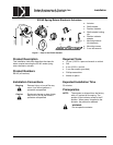
ES142 Spring Return Electronic Actuators
129-270 EAI/ES-6 DEI, Inc.
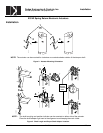
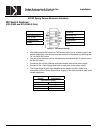
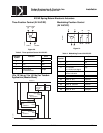
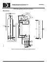
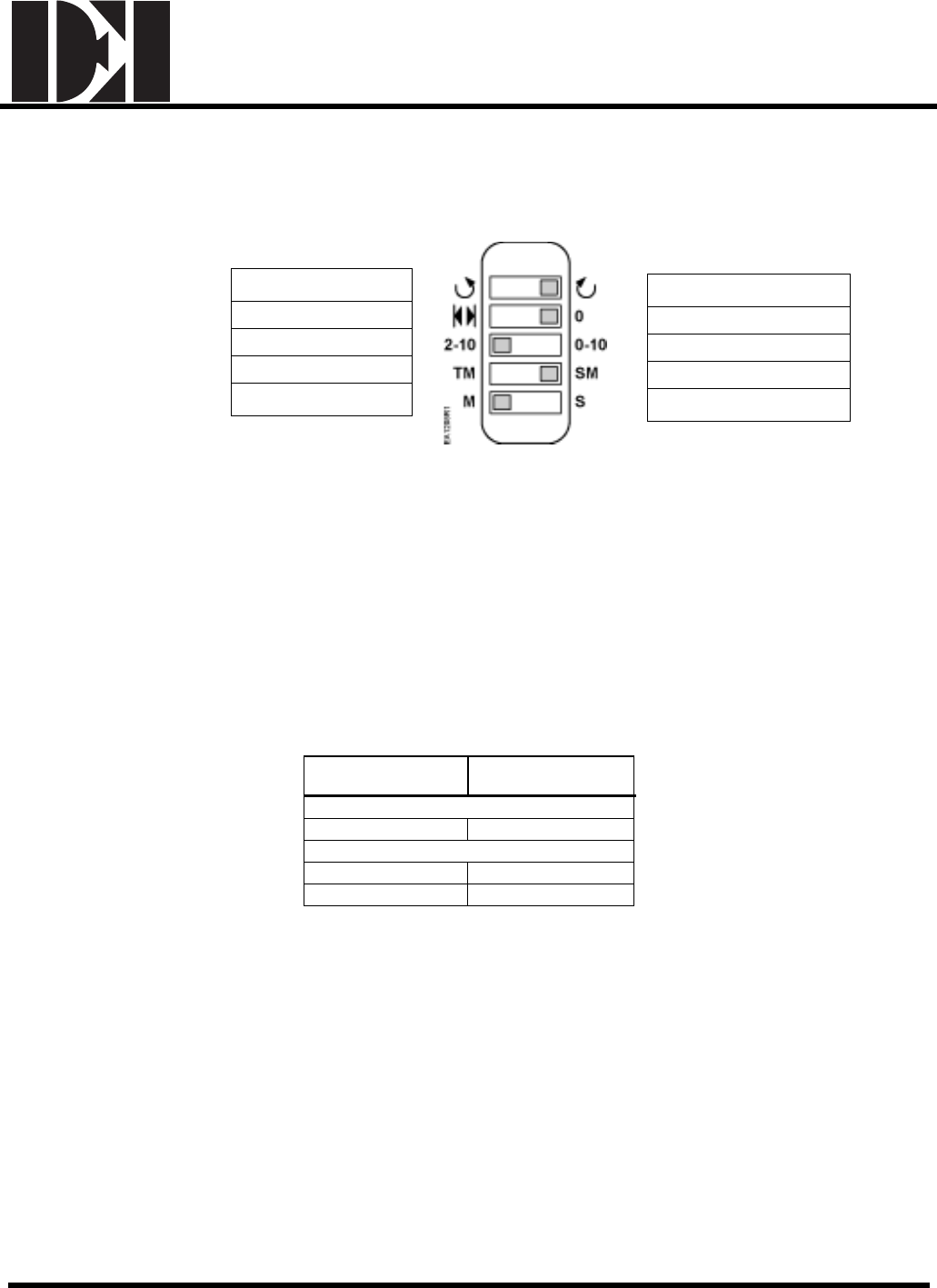
DIP Switch Features
(ES142-M2 and ES142-M2-S Only)
Counterclockwise
Self-adapt feature
2 to 10 Vdc
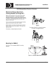
Tandem Mount
Master
Clockwise
Self-Adapt Off
0 to 10 Vdc
Single Mount
Slave
Figure 11. DIP Switch Settings.
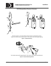
• After setting the 4th DIP switch for TM (tandem mount) on all actuators used in the
tandem application, one actuator must be identified as the Master by selecting the
"M" on the 5th DIP switch.
• The rest of the actuators used in the application should have the "S" (slave) set on
the 5th DIP switch.
• Connect all the 2 (black) Neutral wires and connect them to the power supply.
• Connect all the 1 (red) Supply wires and connect them to the power supply.
• The Output Signal 9 (pink) wire identified as the Master actuator, needs to be
connected to all the Control Signal Wires 8 (gray) of the slave actuators used in the
tandem application.
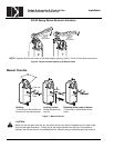
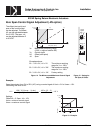
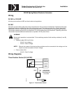
Operating
Voltage
Power
Consumption
Modulating Control
24 Vac/dc 9 VA/7W
2-Position and 3-Position Control
24 Vac/dc 8 VA/6W
120 Vac 9 VA