


Dodge Engineering & Controls, Inc.
Toll Free (877) 334-2875 Fax: (978) 244-1422
Installation
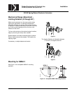
ES142 Spring Return Electronic Actuators
129-270 EAI/ES-15 DEI, Inc.
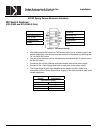
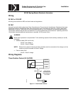
Modulating Control, 24 VAC/DC
1. Check that the wires are connected correctly.
2. Check that the offset (start point) and span are set correctly, if used.
3. Connect wires 1 (red) and 2 (black) to a Digital Multimeter (DMM) with the dial set at VAC to verify that the
operating voltage is within range.
4. Check operation:
a. Connect wires 1 (red) and 2 (black) to the actuator.
b. Set the DMM dial to VDC for the actuator input signal as required for voltage.
c. Connect wires 2 (black) and 8 (gray) to DMM.
d. Apply a full scale input signal (10 VDC) to wire 8 (gray).
e. Allow the actuator shaft coupling to rotate from 0 to 90°.
f. Disconnect wire 1 (red) and the shaft coupling returns to the 0 position.
5. Check spring return:
a. Set the DMM dial to VDC.
b. Connect wires 2 (black) and 8 (gray) to DMM.
c. Apply an input signal (5 VDC) to wire 8 (gray).
d. Allow the actuator shaft coupling to rotate half-way.
e. Disconnect wire 1 (red). The spring returns the actuator shaft coupling to the fail 0 position.
f. Connect wire 1 (red) and the actuator moves.
6. Check feedback:
a. Set the DMM dial to VDC.
b. Attach wires 2 (black) and 9 (pink) to the DMM.
c. Apply a full scale input signal to wire 8 (gray). The reading at the DMM should increase.
d. Remove the signal from wire 8 (gray) and the reading at the DMM should decrease and the actuator
shaft coupling returns to the fail 0 position.
7. Check the auxiliary switch A (-S option):
a. Set the DMM dial to OHMS (resistance) or continuity check.
b. Connect wires S1 and S3 to the DMM. The DMM should indicate an open circuit or no resistance.
c. Apply a full scale input signal to wire 8 (gray). The DMM should indicate contact closure as the actuator
shaft coupling reaches the setting of switch A.
d. Connect wires S1 and S2 to the DMM. The DMM should indicate an open circuit or no resistance.
e. Stop the signal to wire 8 (gray).
f. The DMM should indicate contact closure as the actuator shaft coupling reaches the setting of switch A.
8. Check the auxiliary switch B (-S option):
a. Set the DMM dial to OHMS (resistance) or continuity check.
b. Connect wires S4 and S6 to the DMM. The DMM should indicate an open circuit or no resistance.
c. Apply a full scale input signal to wire 8 (gray). The DMM should indicate contact closure as the actuator
shaft coupling reaches the setting of switch B.
d. Connect wires S4 and S5 to the DMM. The DMM should indicate an open circuit or no resistance.
e. Stop the signal to wire 8 (gray).
f. The DMM should indicate contact closure as the actuator shaft coupling reaches the setting of switch B.
Service
WARNING:
Do not open the actuator. If the actuator is inoperative, replace the unit.