


Dodge Engineering & Controls, Inc.
Toll Free (877) 334-2875 Fax: (978) 244-1422
Installation
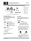
EN221 and EN310 Non-Spring Return Electronic Actuators
Start-Up/Commissioning
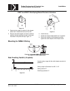
Three-Position Control, 24 VAC
1. Check that the wires are connected correctly.
2. Connect wires 1 (red) and 6 (violet) to a Digital Multimeter (DMM) with the dial set at VAC. Apply a control
signal (24 VAC) to wire 6 to verify that the operating voltage is within range.
3. Connect wires 1 (red) and 7 (orange) to a DMM with the dial set at VAC. Apply a control signal (24 VAC) to
wire 7 to verify that the operating voltage is within range.
4. Check operation:
a. Connect wire 1 (red) to the actuator.
b. Apply a control signal (24 VAC) to wire 6 (violet).
c. Allow the actuator shaft coupling to rotate from 0 to 90°.
d. Stop applying a control signal (24 VAC) to wire 7 (orange).
e. Apply a control signal (24 VAC) to wire 7 (orange).
f. Allow the actuator shaft coupling to rotate from 90 to 0°.
5. Check auxiliary switch A (-S option):
a. Set the DMM dial to OHMS (resistance) or continuity check.
b. Connect wires S1 and S3 to the DMM. The DMM should indicate an open circuit or no resistance.
c. Apply a 24 VAC signal to wire 6 (violet).
The DMM should indicate contact closure as the actuator shaft coupling reaches the setting of switch A.
d. Stop applying a control signal to wire 6 (violet).
e. Connect wires S1 and S2 to the DMM. The DMM should indicate an open circuit or no resistance.
f. Apply a 24 VAC signal to wire 7 (orange).
The DMM should indicate contact closure as the actuator shaft coupling reaches the setting of switch A.
6. Check auxiliary switch B (-S option):
a. Set the DMM dial to OHMS (resistance) or continuity check.
b. Connect wires S4 and S6 to the DMM. The DMM should indicate an open circuit or no resistance.
c. Apply a 24 VAC signal to wire 6 (violet).
The DMM should indicate contact closure as the actuator shaft coupling reaches the setting of switch B.
d. Stop applying a control signal to wire 6 (violet).
e. Connect wires S4 and S5 to the DMM. The DMM should indicate an open circuit or no resistance.
f. Apply a 24 VAC signal to wire 7 (orange).
The DMM should indicate contact closure as the actuator shaft coupling reaches the setting of switch B.
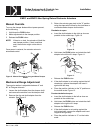
Service
WARNING:
Do not open the actuator. If the actuator is inoperative, replace the unit.
UL Doc. No. 129-272 EAI/EN-9 Dodge Engineering & Controls, Inc.
Rev. 5, Jan., 2005