


Dodge Engineering & Controls, Inc.
Toll Free (877) 334-2875 Fax: (978) 244-1422
Installation
EN221 and EN310 Non-Spring Return Electronic Actuators
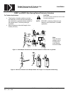
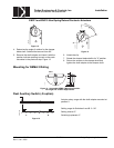
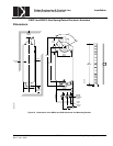
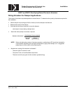
Factory setting:
Switch A 5°
Switch B 85°
To change the settings of A and B:
• Make sure the actuator is in the 0 position. The
scale is valid only in the 0 position.
• Use a flat-blade screwdriver to turn the switch
adjustment dials to the desired setting at which a
signal is to be given.
80
70
60
50
B
90
AUX
SWITCH
ADJ
20
30
40
10
20
40
A
70
EA0304R1
Figure 16. Dual Auxiliary Switch Dials.
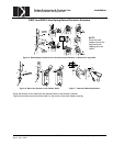
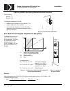
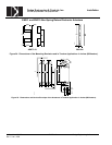
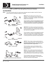
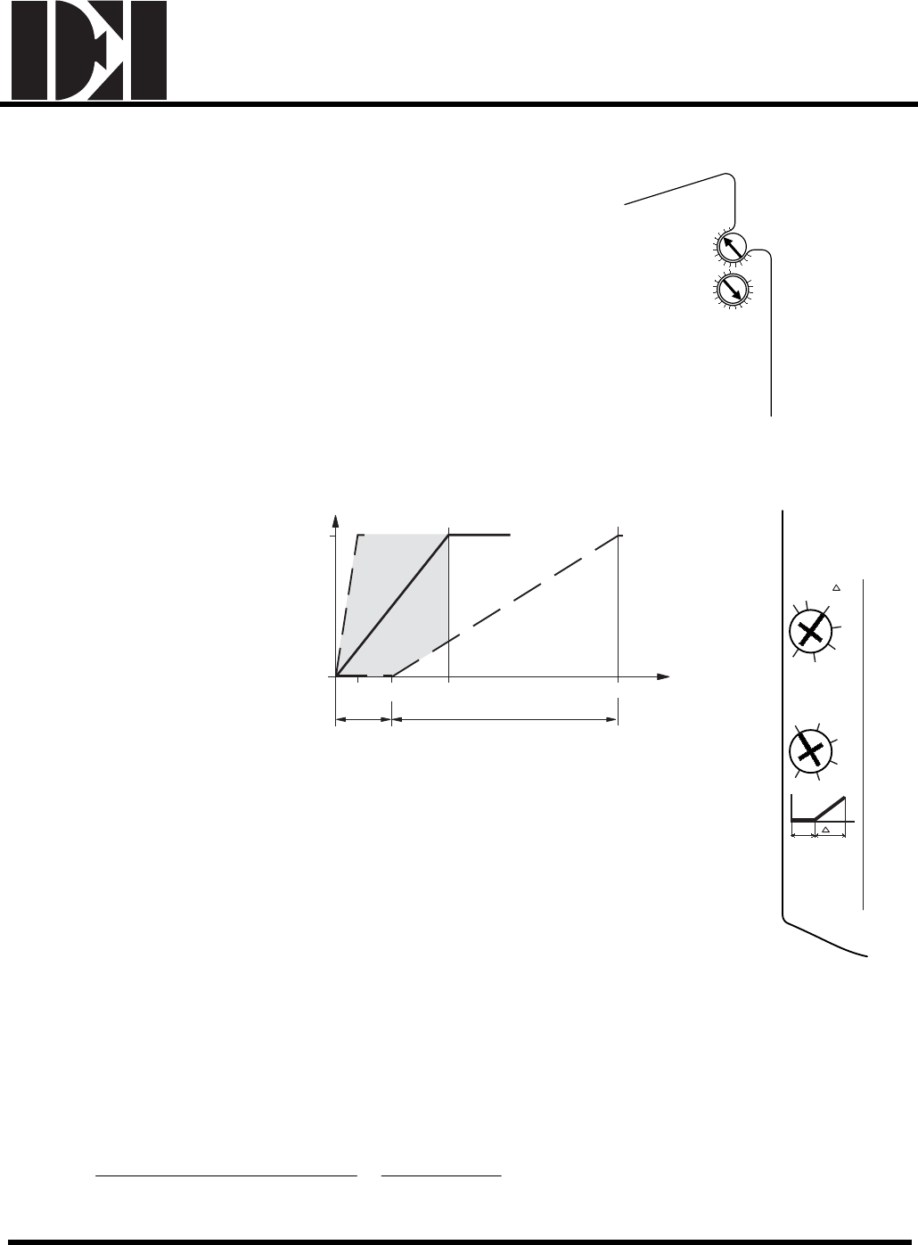
Zero Span Control Signal Adjustment (-ZS option)
The offset (start point) and
span of the control signal
can be adjusted. The offset,
U0, (start point) can be
adjusted between 0 to
5 VDC. The span, ∆U, can
be adjusted between 2 to
30 VDC.
100
0
U
O
∆
U (max. 30 V)
Y
U
(v)
Y
S
(%)
EA0411R1
2 5 10 35
2)1) 3)
Ys Mechanical positioning range
(100% = angle of rotation 90°)
Yu Control signal
U0 Offset (start point)
∆U Span
Examples above:
Ex. 1. U0 = 0V, ∆U = 2V The minimum working
range for Ys = 100%.
Ex. 2. U0 = 5V, ∆U = 30V The maximum working
range for Ys = 100%
Ex. 3. U0 = 0V, ∆U = 10V Factory setting
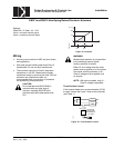
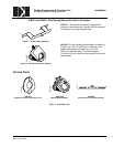
Offset, Uo
2
4
0
1
3
5
Span, U
30
2
15
10
5
20
25
Control
Signals
Uo
U
EA0287R1
Figure 17. The Minimum, Factory Setting, and Maximum
Control Signal Adjustment.
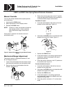
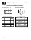
Figure 18. Setting for
10V Span, 0 Offset.
Example:
Open the actuator from 0% to 50% (45°) using a control signal of Umin = 2V to Umax = 10V.
Calculating the value of ∆U:
V16
50
2)(10 x 100
% in rotation of angle Working
min) Umax (U %] [ 100
U =
−
=
−
=∆
UL Doc. No. 129-272 EAI/EN-6 Dodge Engineering & Controls, Inc.
Rev. 5, Jan., 2005