


Dodge Engineering & Controls, Inc.
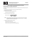
Toll Free (877) 334-2875 Fax: (978) 244-1422
Installation
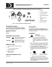
EN221 and EN310 Non-Spring Return Electronic Actuators
PUSH
EA0869R1
a
2
3
4
3
2
a
e
b
d
d
SHAFT
ADAPTER
ALIGNMENT
MARK
c
c
5
4
PUSH
PUSH
PUSH
90
90
6
PUSH
6
5
PUSH
90
90
PUSH
1
>20mm
>3/4 in
<
77 mm
<3 in
>77 mm
>3 in
1
7
PUSH
b
LONGER
SHAFTS
SHORTER
SHAFTS
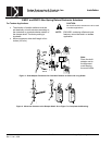
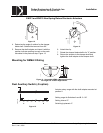
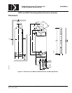
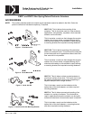
NOTE:
Place the shaft
adapter next to the
alignment mark
keeping the mark
visible.
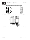
Figure 5. Shaft Adapter Placement for Counterclockwise Rotation on Short and Long Shafts.
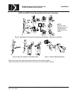
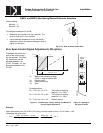
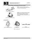
Figure 6. Mount the Actuator to the Damper Shaft. Figure 7. Attach the Mounting Bracket.
EA0356R1
1
2
EA0362R1
3
PUSH
4 4
3
PUSH
EA0357R2
4 mm
5/32 in.
2 PLACES
6
5
1/2
1/2
g
f
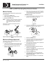
Place the actuator on the shaft with the damper blades in the desired 0 position.
Tighten the middle screw so that the shaft is in the center of the shaft adapter opening.
UL Doc. No. 129-272 EAI/EN-3 Dodge Engineering & Controls, Inc.
Rev. 5, Jan., 2005