


Rev. 1.3 Page 6 of 8 4/25/2008
http://www.delorme.com/gpsmodules
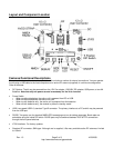
• Power Indicator (right-side Bi-color LED)
• DC On, Battery Good = Green
• DC On, Battery Weak = Yellow-Orange
• DC Off or not present, Battery Weak = Red
• Other conditions = No indication
• Reset Switch: Available from the front panel. Signals a reset directly to the module; observable on the User
Connectors (Refer to schematic).
• Battery Holder: 2 AA in coin-type holder (end-to-end), accessible under the lid.
• User Connector: Accessible under the lid for probing and or custom development. One connector is 20 pins
and one is 24 pins; both are shrouded headers The headers expose 24 user I/O pins (with some restrictions), 7
DC voltages, multiple ground connections, and five special functions. Refer to the schematic for detailed
description of each pin function.
• 3-Pin Header: Used to select module type (affects positions 2 and 3 of the DIP Switch).
• DIP Switch functions (0 = Open, 1 = Closed, X = Don’t Care) [default configuration = all open]
• Switch 1,2,3,4,5 = For future features.
• GPS Signal Indicator (left Bi-color LED), signaled from the module
• PPS available (acquiring) = Flashing Red
• Track Lock = Green
• Track and PPS = Yellow-Orange
• A normal sequence will be flashing red during acquisition followed by green alternating with yellow-orange
every second once a fix is achieved.