


5
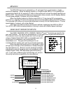
Wiring the control box into the vehicle.
+12V
Connect the +12V terminal to accessory power from the fuse panel or vehicle wiring
harness. This terminal should have power when the key is on or in accessory position. In
addition to powering the display system, this is also where the voltmeter gauge senses the
vehicle electrical system voltage.
Use 20 AWG or larger wire to ensure the system gets good power.
Never connect this to a battery charger alone. It needs to have a 12 volt battery
connected to it. Battery chargers have an unregulated voltage output that will cause the system
to not operate properly.
GROUND
This is the main ground for the display system. A wire should be run from this terminal to
the vehicle’s main ground location at the chassis or engine block. This ground wire should also
be connected to the control box case. One of the mounting screws or case lid screws can be
used for this. Do not use the dash or a dash support brace for the ground connection.
Use 18 AWG or larger wire to ensure sufficient grounding. Proper vehicle grounding is
extremely important for the gauges to read and operate correctly. The engine block should
have heavy ground cables to the battery, frame, firewall, and body. Failure to properly ground
the engine block or the control box can cause incorrect or erratic operation.
DIMMING
The gauges are designed to dim down when the headlights are turned on. This is to
reduce the display intensity at night so the gauges do not cause eye strain or reduced night
vision. Connect this to the tail light or parking light circuit so that it has 12 volts whenever the
headlights are on. When this terminal does not have power the display system will be at full
brightness. When power is applied, the display dims to an adjustable level. The night
brightness level is adjustable two different ways.
The default method is to have the system to dim to a preset level when the lights are
turned on. This brightness is adjusted by turning the shaft protruding from right side of the
control box, next to the display system connector. Turning the shaft clockwise will decrease the
brightness. The shaft will rotate ¾ turn from stop to stop. Do not attempt turn it past the stops.
See DIM ADJ for a description of the second method.
DIM ADJ
The second method allows you to have a dash mounted control to vary the brightness
while the headlights are on. This requires a 10k potentiometer or Dakota Digital’s DIM-1 kit. A
stock headlight rheostat will not work. The dash mount dimmer has two wires, one connects to
the DIM ADJ terminal and the other connects to ground. To allow the dash mount dimmer to
have full control, the shaft on the side of the control box must be turned fully counter-clockwise.
The dash mount dimmer will only vary the display brightness when the DIMMING terminal has
power.