


19
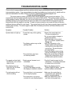
Symptom Possible Problem Solution
-----------------------------------------------------------------------------------------------------------------------------------
The gear shift indicator The optional gear shift sending Connect the sending unit to the
does not light up. unit is not connected to the control box using the
control box. instructions supplied with the
sending unit.
The gear shift indicator The gear shift sending unit Check the connections to the
does not operate is not connected properly. transmission linkage and to
properly. the control box.
Connect 12 volts to the sending
unit power wire.
The colored bulbs in The LED bulbs are not Connect the wires found on the
the display panel for connected into the auto's back of the aluminum panel
turn signals and high electrical system. to your cars electrical system
beam do not light up. (these are not wired into the as explained in the Optional
(not found on all units) display system control box) Indicators section of the manual.
The internal turn signal The control box is not connected Check the wires connected to the
and high beam to the vehicle's electrical HIGH, LEFT, and RIGHT
indicators do not light up. system properly. terminals on the control box.
The check engine The control box is not connected This feature is designed to work
indicator does not to a TPI control module. with engine control systems that
operate properly. provide an active low signal.
The check engine The Engine Control Module Connect a light or similar load
indicator stays on (ECM) needs to see the to the ECM along with the
all of the time. load of a light connected to it. control box.
Trip select and trip reset Select and reset switches are Momentary push-button or toggle
functions do not operate not connected to the control switches must be connected to
properly. box. the TRIP and RESET terminals
as described in the Trip meter
section of the installation manual
The wrong type of switch is The switch terminal connected
being used. to the control box should
normally be open. When the
the switch is activated, the
terminal should make contact
to ground.
The display system starts The TRIP terminal is constantly Disconnect or replace the trip
up in the demonstration connected to ground. select switch.
mode and remains in it.
The speed always shows The WRN terminal is constantly Check wiring to the WRN
“AdJ”. connected to ground. terminal for a short to ground.