


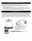
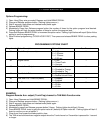
IGNITION SWITCH WIRING
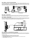
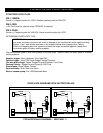
6 PIN HIGH-CURRENT SPADE CONNECTORS:
PIN 1: RED 14Ga.: BATTERY CONSTANT FUSED 30A
PIN 2: BROWN 14Ga.: STARTER OUTPUT - 30A
PIN 3: GRAY 14Ga.: IGNITION 2 - 30A
PIN 4: WHITE 18Ga.: + PARKING LIGHTS 10A SEE NEXT PAGE
PIN 5: PINK 14Ga.: IGNITION 1 - 30A
PIN 6: RED 14Ga.: BATTERY CONSTANT FUSED - 30A
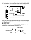
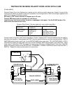
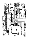
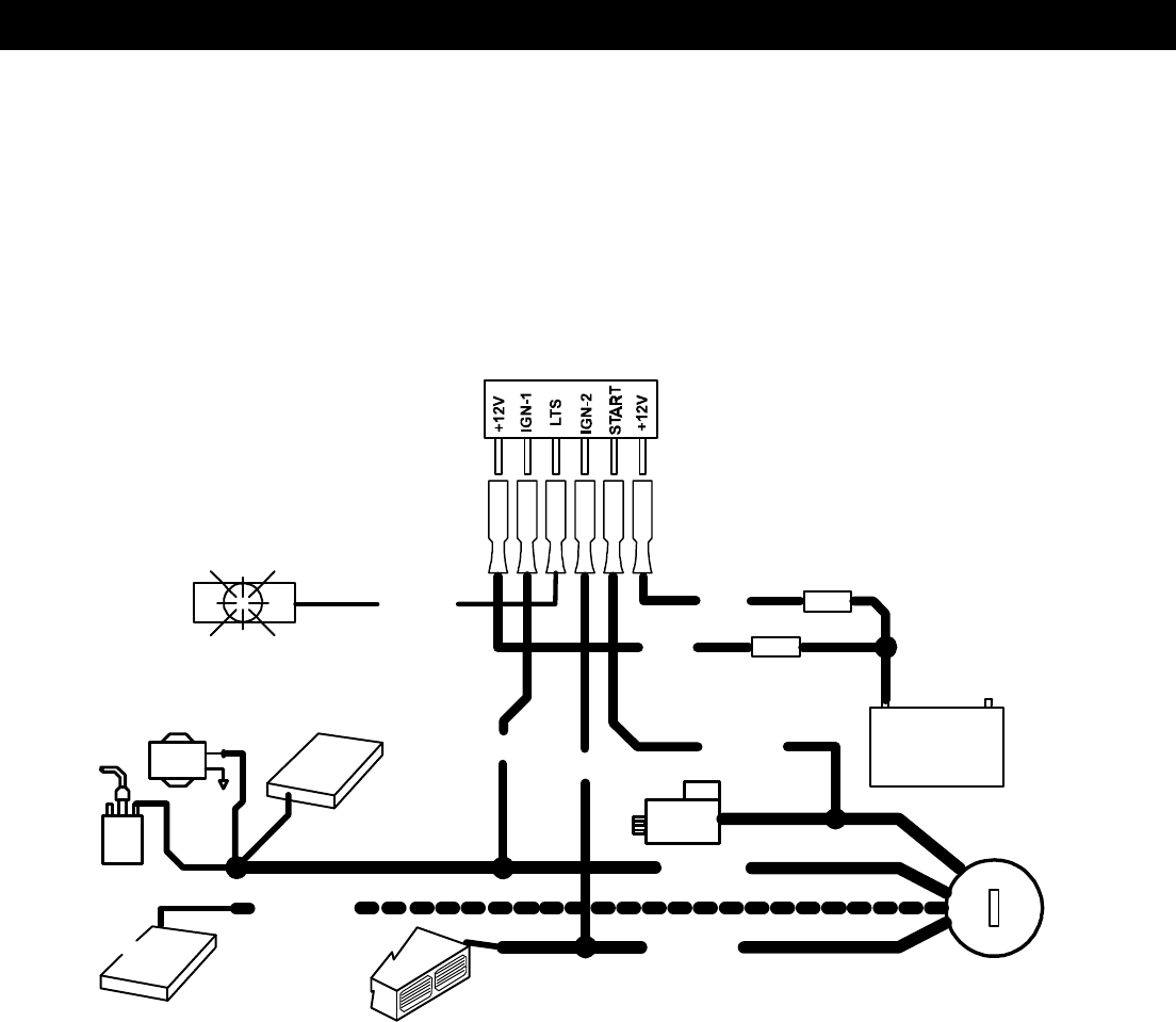
See diagram below for connection information:
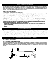
SPADE PIN 4: WHITE: (+) PARKING LIGHT OUTPUT [10 AMP MAX.]
(WHITE OUTPUT WIRE MUST BE FUSED OR SERIOUS DAMAGE MAY OCCUR.)
On most AMERICAN and JAPANESE vehicles, the parking lights will operate on a single fused circuit. You may
connect WHITE wire directly to the wire of any parking light or at main lighting switch.
NOTE: Some JAPANESE vehicles use a negative triggered relay to activate parking lights. Use a relay to convert
to ground switch or tap into the positive circuit of the parking lights after the Factory relay. On most EUROPEAN
vehicles, the light circuits are separately fused for left and right. Each circuit must be individually connected and
isolated from one another. This can be done by using two (2) 6A05 6 Amp diodes, OR one (1) BOSCH SPST dual
output relay (part no. 0-332-015-001).
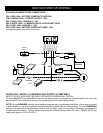
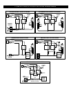
PARKING
LIGHTS
FUSE
RED
WHITE
30A
FUSE
RED
+10A MAX.
30A
+
-
BROWNPINKFUEL
ENGINE
BATTERY
PUMP
ECU
GRAY
+
STARTER
-
COIL
IGN 1
2nd IGN 1
OR
TRANSMISSION
2nd IGN 2
IGN 2
ECU
H/V/AC