


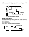
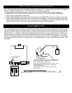
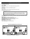
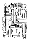

PIN 2: ORANGE: MULTI-FUNCTION OUTPUT 2
Output 2 comes pre-programmed to operate as the Anti-Grind/Starter Disable output. It can also be used for the
sensor disable circuit for a host alarm. This output activates whenever a remote start is requested, and when the
vehicle is remotely locked with the transmitter. Connect this wire to terminal 85 of a relay. See diagram below.
PIN 3: BLACK: MAIN SYSTEM GROUND
Connect to chassis metal of the vehicle. An existing bolt or screw MAY provide an adequate ground, or drill a small
hole, scrape away paint and attach using a sheet metal screw & star washer. If this wire is not connected OR
connected to a point on the vehicle that provides a poor ground, undesirable and inconsistent operation will occur.
This is a mandatory connection.
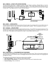
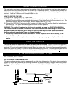
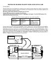
PIN 4: YELLOW: IGNITION 1
NEGATIVE (-) OUTPUT FOR RELAY
Use this wire when the vehicle requires a second IGNITION1, IGNITION2, or ACCESSORY wire to be activated.
This occurs commonly in Toyota, and late model GM cars. See diagram below:
TO
IGN 2
MOTOR
ACC
START
CUT
BROWN
OPTIONAL
RELAY
OPTIONAL 1N4001 DIODE
OPTIONAL LED
USE WITH LED ONLY
RECOMMENDED
ORANGE
8685
FOR VEHICLES
WITHOUT DOORLOCKS
MAKE CERTAIN TO CONNECT "BROWN" START OUTPUT WIRE TO
MOTOR SIDE OF ANTI-GRIND/START DISABLE RELAY.
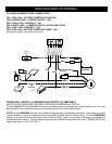
IGN 1
CONNECT TO "GRAY IGN 2" WIRE
WHEN WIRING RELAY FOR IGN 2
YELLOW
OR
CONNECT TO BATTERY FOR IGN 1
85
86
INSERT DIODE AS SHOWN
WHEN CONNECTING FOR "IGN 2"
+
-
30 87
BATTERY
2nd IGN 1
OR
2nd IGN 2