


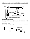

TESTING FOR REVERSE POLARITY DOOR LOCKS WITH A VOM
(5-wire switch)
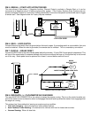
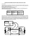
Reverse Polarity Door Lock Systems are a series circuit in which one switch serves as a "master" source for the
motor grounds. When any switch in the circuit is pressed, one of the grounds is "lifted" and voltage is applied to the
open circuit causing the locks to activate.
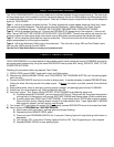
Set meter to VOLT scale sufficient to measure up to 15 volts.
Connect RED meter probe to constant +12 volt source.
Locate the door lock wires in either the driver or passenger’s kick panel. Use the BLACK probe of the
meter check the wires one at a time:
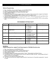
Common Wire Colors: (Use as a guide only, your vehicle may differ.)
FORD / LINCOLN
MERCURY
DODGE / CHRYSLER
PLYMOUTH
GENERAL MOTORS
Pink/Lt. Green Orange/Violet Lt. Blue
Pink/Yellow Pink/Violet or Dark Blue or Black
Orange* Black/White (Trucks)
Pink* Black/Red (Trucks)
*There may be (2) wires of the same color
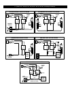
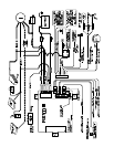
Connect meter to first wire, meter should read about 12 volts. Press the LEFT door lock switch to the lock position,
and then unlock position. Now presses the RIGHT door lock switch to the lock, and then unlock positions. If BOTH
SWITCHES make the wire read 0 volt, it is the WRONG WIRE (it's a motor wire). TRY ANOTHER WIRE. If ONLY
ONE SWITCH makes the meter read 0 volt, then it is the CORRECT WIRE and that switch is the "MASTER". When
meter reads 0 Volts when LOCK is pressed, that wire is the LOCK wire. If Meter Reads 0 Volts when UNLOCK
position is pressed, that wire is the UNLOCK wire. REMEMBER - CORRECT WIRES will show 0 volts from ONLY 1
SWITCH. Repeat the test procedure above for second wire.
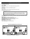
12.0 +
COM
AC
V
DCV
V-
OFF
PASSENGER DOOR
DRIVER'S DOOR
LOCK SWITCH
MASTER SWITCH
+12V
VEHICLE INTERIOR
LEFT DOOR
RIGHT DOOR
LOCK MOTOR
DOOR JAMBS
LOCK MOTOR