


COMPONENT MOUNTING
DO NOT mount the control unit in the engine compartment. DO NOT Mount the control unit or wiring harness
where they can become entangled with moving parts such as brake/gas/clutch pedals, or the steering column.
The alarm control module should be mounted in a concealed location. The antenna wire should be routed
away from any metal if possible. DO NOT alter the length of the antenna wire, route it with other wires, or
ground it.
SIREN MOUNTING: Mount the siren under the hood to fender-well or other body surface with the open end facing
downward. Run the red siren wire through the firewall using a rubber grommet. Ground the black wire to the body
metal near the siren.
LED: Mount the red LED in a visible location on the dashboard or console.
Shock Sensor: Mount the included shock sensor with wire ties to an under dash wire harness or fasten with screws to
firewall or side paneling.
Override/Program Button: Mount the Override/Program push-button in a hidden, but accessible location to the user
in case the system must be disarmed without the use of the transmitter. This switch is also used to program certain
features.
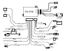
WIRING
GRAY WIRE: (-) AUX REMOTE OUTPUT 1 (Optional, May Require Relay)
Connects to terminal 85 of a relay. Connect terminal 86 to constant. Connect terminal 87 to +12V constant or ground
depending on the type of circuit that needs to be activated. Connect terminal 30 to the device/circuit to be activated.
BLACK/WHITE WIRE: (-) DOME LIGHT ILLUMINATION (Optional, May Require Relay)
Connect to terminal 85 of relay. Connect terminal 86 to constant. Connect terminal 87 to +12V constant or ground
depending on the type of dome light circuit in the vehicle. 30 to the dome light circuit.
ORANGE WIRE: (-) NEG. ARMED OUTPUT / STARTER DISABLE (300mA Negative)
Ground output when system is armed. This output is used for disabling the starter or to activate other devices such as
scanner LED’s, window modules, voice modules etc. For starter kill, cut starter wire and connect between 87A and 30
on relay. Connect orange wire to 85 and connect 86 to an Ignition source that has voltage in the ON and CRANKING
position.
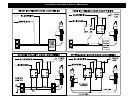
BLUE/WHITE WIRE: (-) NEG. DOOR LOCK OUTPUT
Connects to lock circuit of NEGATIVE door lock systems or to terminal 85 of a relay. See Door Lock diagrams PG 7.
WHITE/RED WIRE: (-) NEG. DOOR UNLOCK OUTPUT
Connects to unlock circuit of NEGATIVE door lock systems or to terminal 85 of a relay. See Door Lock diagrams. PG 7