


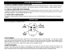


WIRING
PIN 8: BLACK WIRE: CHASSIS GROUND
THIS WIRE MUST BE CONNECTED TO THE CHASSIS METAL OF THE VEHICLE. Scrape away any paint or dirt to
ensure a good connection. We recommend the kick panel area for your ground point.
PIN 9: WHITE WIRE: +12V FLASHING PARKING LIGHT OUTPUT (Optional)
Connect to switched parking light wire at back of light switch. If this is not possible, connect directly to one of the
parking lights at the front of the vehicle. European vehicles require separate right and left circuits. Use a dual relay or
2 diodes to separate the output signal.
PIN 10: GREEN WIRE: (-) DOOR TRIGGER
Connect to Negative type door switches that read ground when a door is opened and 12 volts when all doors are
closed. In the case of isolated door triggers, you may need to run additional wires from other doors OR go directly to
the wire that triggers the vehicle’s dome light.
PIN 11: YELLOW WIRE: IGNITION SWITCHED “ON” and “START” +12 VOLTS
Connect to a an Ignition Wire (or Fuse in the fuse box) that shows +12 Volts when the key is in both the “On” and
“Start” positions.
PIN 12: ORANGE WIRE: NEGATIVE ARMED OUTPUT (500mA Ground)
Ground output when system is armed. This output can be used for an additional starter disable or to activate other
devices such as scanner LED’s, Window Roll-up modules, etc.
PIN 13: WHITE/RED WIRE: (-) AUX REMOTE OUTPUT 2 (Optional, requires relay)
Connect to terminal 85 of a relay or to the negative trigger input of an auxiliary device such as a Remote Start or
Window Control Module.
PIN 14: BLUE WIRE: (-) HOOD/TRUNK TRIGGER
Input trigger for a grounding hood or trunk pin switch. Connect to existing hood and trunk pin switches that read
ground when open. If no existing switches are available, install new grounding pin switches if desired. Note: DO NOT
mount new pin switches in water pathways.
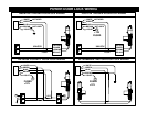
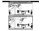
PIN 15: BROWN/WHITE WIRE: (-) HORN HONK/CHIRP OUTPUT (Optional, requires relay)
Connects to terminal 85 of a relay. Connect terminal 86 to +12V Constant. Connect terminal 87 to +12V or ground
depending on the type of horn circuit in the vehicle. Connect terminal 30 to the horn activation circuit.
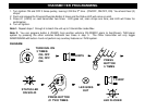
2-PIN PLUG (BLUE): PROGRAM/OVERRIDE PUSH BUTTON
2-PIN PLUG (RED): LED INDICATOR (RED FLASHING LIGHT)