


6
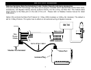
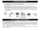
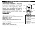
WIRING: SHOCK SENSOR
4 PIN SENSOR PLUG/HARNESS (BLUE):
White Wire: Negative Trigger
Blue Wire: Negative Warn-away
Black Wire: Sensor Ground
Red Wire Sensor Power
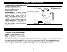
SHOCK SENSOR: The sensor supplied
with this system does not require any
additional wiring. Simply mount the
sensor in a suitable location, plug it in,
and adjust the sensitivity. There are 2
LED’s on the shock sensor to assist you
in adjusting sensitivity. The Green LED
indicates the “Warn Away” level and the
Red LED indicates a full alarm shock
sensor violation.
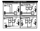
POWER DOOR LOCK WIRING
3 PIN DOOR LOCK PLUG (Optional):
GREEN: (-) Negative pulse for LOCK
RED: +12V Coil Power for using relays.
BLUE: (-) Negative pulse for UNLOCK
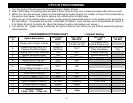
Hint: Determine the type of locking system the vehicle has before connecting any wires. Incorrect connection
could result in damage to the alarm and/or the vehicle’s locking system. Some vehicles are equipped with
Class 2 DATA door locks systems which require a bypass module to control the door locks. Please refer to
vehicle wiring color chart which is supplied via TechWeb (basic service) for authorized dealers.
GREEN LED
RED LED
PRE-WARN
TRIGGER
GROUND
12 VOLTS
WHITE
BLUE
BLACK
RED
SENSITIVITY
ADJUSTMENT
(Trigger)
(Pre-Warn)
SENSOR ADJUSTMENT
Clockwise = Higher Sensitivity
Counter Clockwise = Lower Sensitivity
1) Start adjustment by turning sensitivty at
minimum.