


3
3
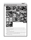
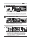
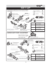
a. Build the throttle/brake linkages as shown on the diagram.
b. Secure the brake cam lever onto brake cam with set screw.
c. Install the servo horn onto throttle sero output shaft.
INSTALLING THROTTLE LINKAGE
skip if already assembled
c
b
a
2
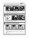
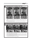
INSTALLING STEERING SERVO LINKAGE
skip if already assembled
a b
c
c
a. Install the steering linkage rod onto steering servo horn.
b. Plug the steering linkage rod into the hole on the steering servo saver arm.
c. Install the servo horn onto steering servo output shaft. (In neutral, servo horn should be pointing
straight up, the steering arm should be pointing straight forward.)
d. Reassemble the radio plate onto the car with its original screws.(8 on the plate and 2 on the chassis)
d
d
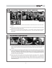
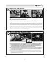
a. Plug the charger into an AC outlet, and then pull on the igniter lever to accept the charging adapter.
b. At this point, the small red LED indicator on the charger should light up indicating the charging sequence
is in progress.
c. When the charging complete, pull on the glow plug igniter lever to unplug the glow igniter.
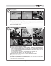
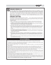
Charge the new glow plug igniter for 16 to 24 hours on the first charge. For subsequent charges, charge
it about 12 hours before next use.
NOTE:
If the igniter gets warm or hot during the charge, unplug the igniter from charger immediately. A warm /
hot igniter means the igniter is overcharged. Overcharging can damage the internal battery in the igniter;
thus, shortening its life.
CHARGING THE GLOW PLUG IGNITER
4
a b c
Thunder Tiger Optional Part #2165, 1300MAH Glow Starter w/220V Charger.
Thunder Tiger Optional Part #2166, 1300MAH Glow Starter w/110V Charger.
To brake cam
To engine
carburetor
lever