


5
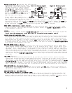
Parking Light Output (-) (Optional Part #775 required)
Probe the wire(s) coming from your head-
lamp switch. Find the wire that will show
+12V when the parking lights are ON and
ground when the lights are OFF. Connect
the YELLOW wire from Part #775 to this wire.
Connect the BROWN wire from the 11-pin
harness to the WHITE wire on Part #775.
Connect the BLACK and the BLUE wires from
part #775 to +12V constant fused at 20
amps. See “positive” diagram.
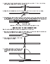
If your vehicle has a negative (-)
parking output. When probing the wire(s)
coming from your headlight switch, find
a wire that shows (-) negative or ground when the parking lights are on and positive or neutral when
the parking lights are off. Connect the YELLOW wire from Part #775 to this wire. Connect the BROWN wire
from the 4-pin harness to the WHITE wire on Part #775 connect the BLACK wire to 12V constant fused at
20 amps and connect the BLUE wire from Part #775 to ground. See “negative” diagram.
BRAKE INPUT - Some vehicles require “key on”.
The brake wire is located on the switch near and above the brake pedal. The correct wire will show
(+12V) on the test light only when the brake is pressed. Connect the BLUE WITH BLACK STRIPE from the
11-pin harness to this wire.
ANTENNA
For best results, run the antenna (YELLOW WITH BLACK TIP in the 11-pin harness) as straight as possible.
Do not place the antenna next to any metal parts or the vehicle’s main computer control.
FACTORY ALARM SHUT DOWN WIRE (FASD)
If your vehicle is equipped with a factory alarm system (as most vehicles with a factory keyless entry
are) and you can disarm your factory alarm by using the key in the door you will need to use the FASD
wire. Probe for a small gauge wire (usually found in the driver’s side kick panel) that shows ground
when the door lock cylinder is turned to the unlock position using the door key. This wire will usually
show a positive voltage before turning the key. NOTE: Some factory disarm wires remain neutral (shows
no voltage) before you turn the key to unlock instead of +12v positive. Connect the RED WITH BLACK STRIPE
wire from the 11-pin harness to this wire.
HOOD PIN SWITCH (Mandatory Hookup)
This feature will keep the engine from starting or shut off the engine when the hood is opened when
remote started. Locate a good chassis ground, if at all possible do not install the pin switch in the
rain gutter. Drill a 5/16 hole, insert the pin switch into the hole and tighten. Check for the hood
adjustment, there is approximately 1/4” adjustment in the pin switch. Close the hood easy, making sure
that the pin switch is not keeping the hood from closing all the way. If it does, cut off approximately
1/8” of the black plastic off of the top of the hoodpin switch and try closing the hood again. Check
to make sure that the hoodpin switch remains neutral when the hood is closed and shows ground when the
hood is open. Plug the BLACK WITH BLUE STRIPE wire from the 11-pin harness into the bottom of the hood
pin switch.
TACH INPUT (Optional)
By this time, you should have determined the way you want your vehicle to start (tach or tachless).
Tachless uses voltage electronic signals and timing to work. Tach types use a signal directly from the
ignition coil. If you have chosen the TACHLESS start option, simply proceed to the next step and skip
the following instructions. Make sure you tape this wire up if not used. For TACH mode connect the BLACK
WITH WHITE STRIPE wire from the 11-pin harness to the negative side of the coil or the tach wire at
the coil pack under the hood. To find the coil pack follow the spark plug wires back to their beginning
point. To operate in tach mode, make sure to program tach option. See programming tach option page 14.
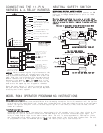
AUXILIARY INPUT (For Aftermarket Alarms)
If you use this starter with an aftermarket alarm, connect the BLUE wire from the 11-pin harness to
the second or third channel output of your existing alarm. When the output is activated, a signal will
activate the remote starter.
AUXILIARY INPUT (For Model RS85 Only)
(For your factory keyless or aftermarket alarm)
When connecting this unit to a factory keyless entry system, you must locate the door lock wire that
tests as a positive when you press the lock button on the factory remote. A relay Part #775 will be
needed to convert the positive output from the door lock to a negative for the RS85. If the wire negative
when you press the lock button on the factory remote, you can tie directly into the BLUE wire.
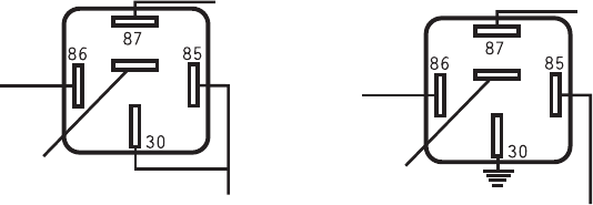
Negative Parking Lights
+12V
Constant
87a
To parking
light wire
in vehicle
+12V Fused
at 20 amps
Brown(-)
from
module
WHITE
YELLOW
GROUND
RED
Do not use,
tape off.
BLACK
Positive Parking Lights
BLACK
87a
To parking
light
circuit
+12V Fused
at 20 amps
Brown(-)
from
module
WHITE
YELLOW
BLUE
RED
Do not use,
tape off.