


2
PRECAUTIONS
Since there are many different makes and models of vehicles, look at the wiring chart on page 17 in this
manual and our website, www.bulldogsecurity.com.
Read this manual thoroughly before starting the installation. You must decide if the parking light option
is desired. If so, an optional Part #775 will be needed.
TACH/TACHLESS OPERATION
In most cases the decision to go with tachless mode will save time during the installation. If your vehicle
is hard-starting then you should use tach mode.
MAKE SURE YOU PLACE THE WARNING STICKER UNDER YOUR HOOD.
For Model RS82 or RS85 follow the instructions until you reach page 13. For RS85 only, continue.
This system is designed for use with vehicles equipped with fuel-injected,
gasoline engines with automatic transmissions only.
SAFETY FIRST!
Never start your vehicle if it is indoors, if the keys are in the ignition and unless you’re sure the car
is in park. A periodic safety check is recommended to ensure that your system is in proper working order.
DO NOT use mechanical wiring connections, such as crimp or snap together taps. Follow instructions on
below.
DO NOT disconnect the battery if the vehicle has an anti-theft-coded radio or is equipped with an airbag.
Doing so may cause a warning light to be displayed and may require a trip to the dealer to be corrected.
DO NOT leave the interior or exterior lights on for an extended period of time as it may cause battery drain.
Remove the dome light fuse from the fuse box. NOTE: Starter systems do not work well with a partially
discharged battery.
DO NOT mount the control module until all connections have been made and tested. Using wire ties or
double sided tape, MOUNT THE MODULE UNDER THE DASH.
WARNING!
GENERAL MOTORS REAR WHEEL DRIVE VEHICLES AND DODGE DAKOTAS
All General Motors rear wheel drive vehicles and Dodge Dakotas built prior to 1996 do not have an
electrical Neutral Safety switch. They have a mechanical neutral safety switch. The mechanical neutral
safety switch operates as follows.
a)The key will only turn to start position when the gear selector is in park or neutral.
b)The key can only be removed from the ignition switch when the gear selector is in the park position.
You must use special precautions with this system.
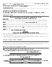
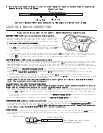
To operate your test probe, connect the black clip to a good chassis ground. Connect the red clip to a good
12V positive source. If the test probe is connected correctly, both the green and the red lights will be dimly
illuminated. If a positive source is probed, the red light will glow bright and the green light will go out.
If a negative source is probed, the green light will glow bright and the red light will go out.
USING YOUR TEST PROBE
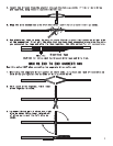
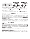
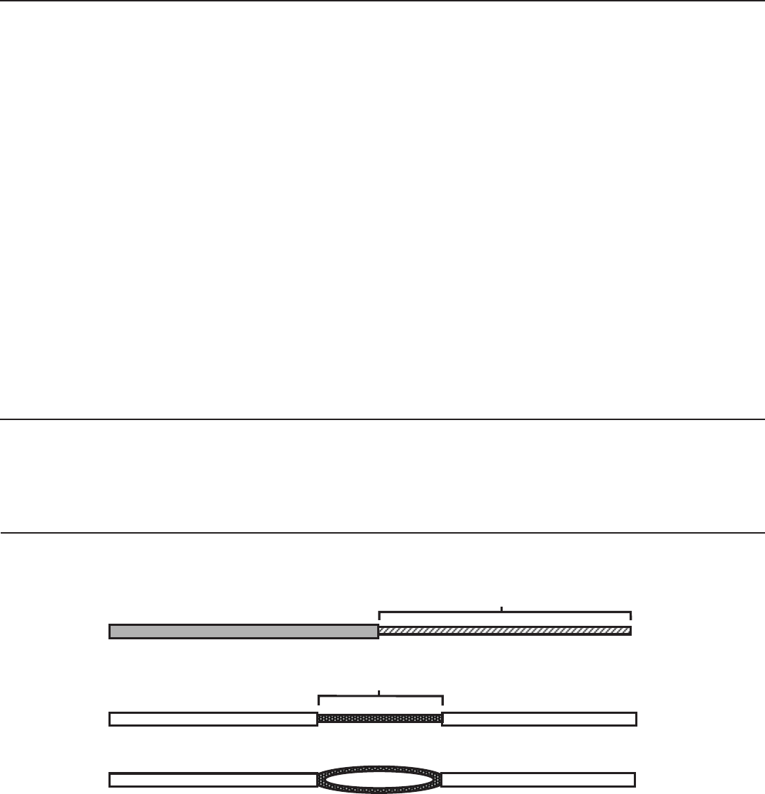
MAKING WIRING CONNECTIONS
NOTE: In most cases you should not cut your vehicle wire in two.
1. Strip back two inches of insulation on the wire from the remote starter.
2. Strip back one inch of insulation on the wire you need to connect to.
3. Separate the vehicle wire as shown. Make the separation large enough to fit the other
wire through.
Two Inches of Bare Wire
One Inch of Bare Wire