8
(-) Negative Dome Light Type (All other vehicles)
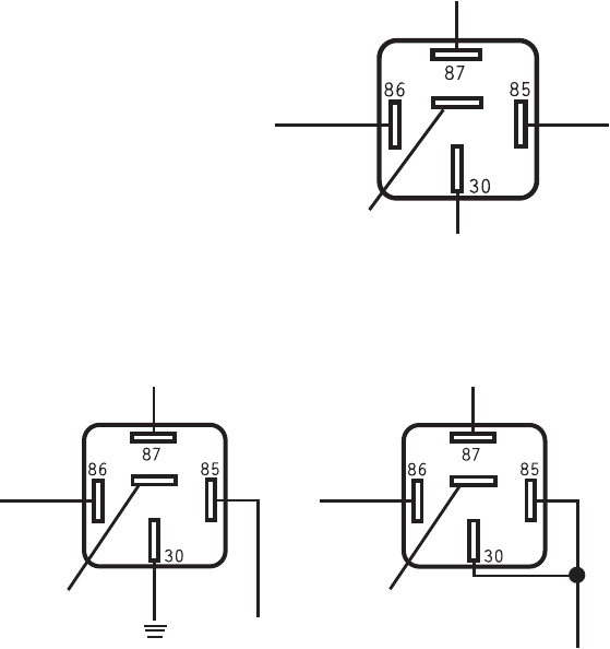
Connect the VIOLET wire from the 18-pin harness to the WHITE wire
on the optional #775 relay harness. Connect the BLACK wire on the
optional relay to +12V constant fused at 5 amps. Connect the BLUE
wire to ground. Connect the YELLOW wire to the dome light circuit.
DO NOT USE THE RED WIRE, TAPE OFF.
87a
To Dome Light
Circuit
+12 VOLT
FUSED AT
5 AMPS
(-) VIOLET
FROM 18-pin
wire harness.
(+) OR (-) Depending
on Door Pin Type
YELLOW
BLACK
WHITE
BLUE
RED
Optional part #775 required.
DOME LIGHT SUPERVISION
If your vehicle is a (+) positive door pin connect the BLACK WITH WITH YELLOW STRIPE wire from the 18-
pin harness to the door pin wire. Follow the instructions on page 11 to program your unit to work with
a (+) positive door pin. If your vehicle is a (-) negative door pin, connect the BLACK WITH WITH YELLOW
STRIPE wire from the 18-pin harness to the door pin wire. Follow the instructions on page 11 to program
your unit to work with a (-) negative door pin.
NOTE: When testing the door pin wire, make sure the dome light is on. Some vehicles, if the door is
left open for a period of time, the dome light will go out, resulting in a false reading.
DOME LIGHT (Optional Part #775 required)
Once you have determined if your door pin wire is a (+) positive or (-) negative and you have made
this connection, next, you must decide if you are going to connect the dome light supervision function
which will require an optional relay. This relay will also need to be connected in a (+) positive or
(-) negative configuration depending on the type of door pin in your vehicle.
SHOCK SENSOR INPUT
The GREEN WIRE on the 18-pin harness is a negative input to be used when installing an external shock
sensor, motion sensor or trunk pin. If this wire is not used, make sure to tape it up.
TRUNK RELEASE OUTPUT (Optional Part #775
required)
Locate the trunk release wire coming from
the back of the trunk release switch. To
determine if your trunk release is tripped
by a (+) positive or a (-) negative (most
trunk release switches are (+) positive).
Place one end of your test light to ground,
press the “Trunk” button, if the test light
illuminates, you have a (+) positive trunk
release. If it does not, connect the test
light to +12V constant and probe the wire.
If the test light illuminates when the
button is pressed, then you have a (-)
negative trunk release.
Connect the WHITE WITH RED STRIPE wire to
the WHITE wire of the optional relay.
Please see diagrams below for correct
connections.
POSITIVE TRUNK RELEASE
NEGATIVE TRUNK RELEASE
Optional part #775 required.
+12 VOLT FUSED
AT 20 AMPS
87a
TO FACTORY TRUNK WIRE
WHITE/RED
FROM ALARM
87a
TO FACTORY TRUNK WIRE
+12 VOLT FUSED
AT 20 AMPS
WHITE/RED
FROM ALARM
YELLOW
BLACKWHITE
BLUE
YELLOW
BLACKWHITE
BLUE
THE RED WIRE IS NOT USED, TAPE OFF.
RED
RED
SIREN OUTPUT (+) (Optional part #724)
Connect the GRAY wire from the 18-pin harness to the RED (+) positive input on the siren. Make sure
you ground the BLACK wire on the siren.


