7
CONNECTING THE 18-PIN HARNESS & 4-RELAY HARNESS
FACTORY ANTI-THEFT SYSTEMS
FOR GENERAL MOTORS CARS ONLY
System 1: PASSKEY I and II system (1985 and up). This system has a resistor pill in the key. Measure
resistance of the pill using a test meter. A bypass module is available, part #VATS-WR module.
System 2: PASSLOCK I and II system (1995 and up). Passlock does not have a pill in the key. It has a
light on the dash that states ANTITHEFT OR SECURITY system. A bypass module is available, part #GMBP-
721 module.
System 3: PASSKEY III system (GM 1998 and up). Passkey III is GMs version of a transponder system. This
key will have the letters PK3 on it. A bypass module is available. (Part #781)
FORD ANTI-THEFT SYSTEM: PATS
Ford uses a bypass part #FBP-718 module, 1995-1998. (1999 and up will use part #781.)
CHRYSLER AND MOST IMPORTS ANTI-THEFT SYSTEM: TRANSPONDER
1998 and up will use part #781.
To order these bypass modules call 1-800-878-8007.
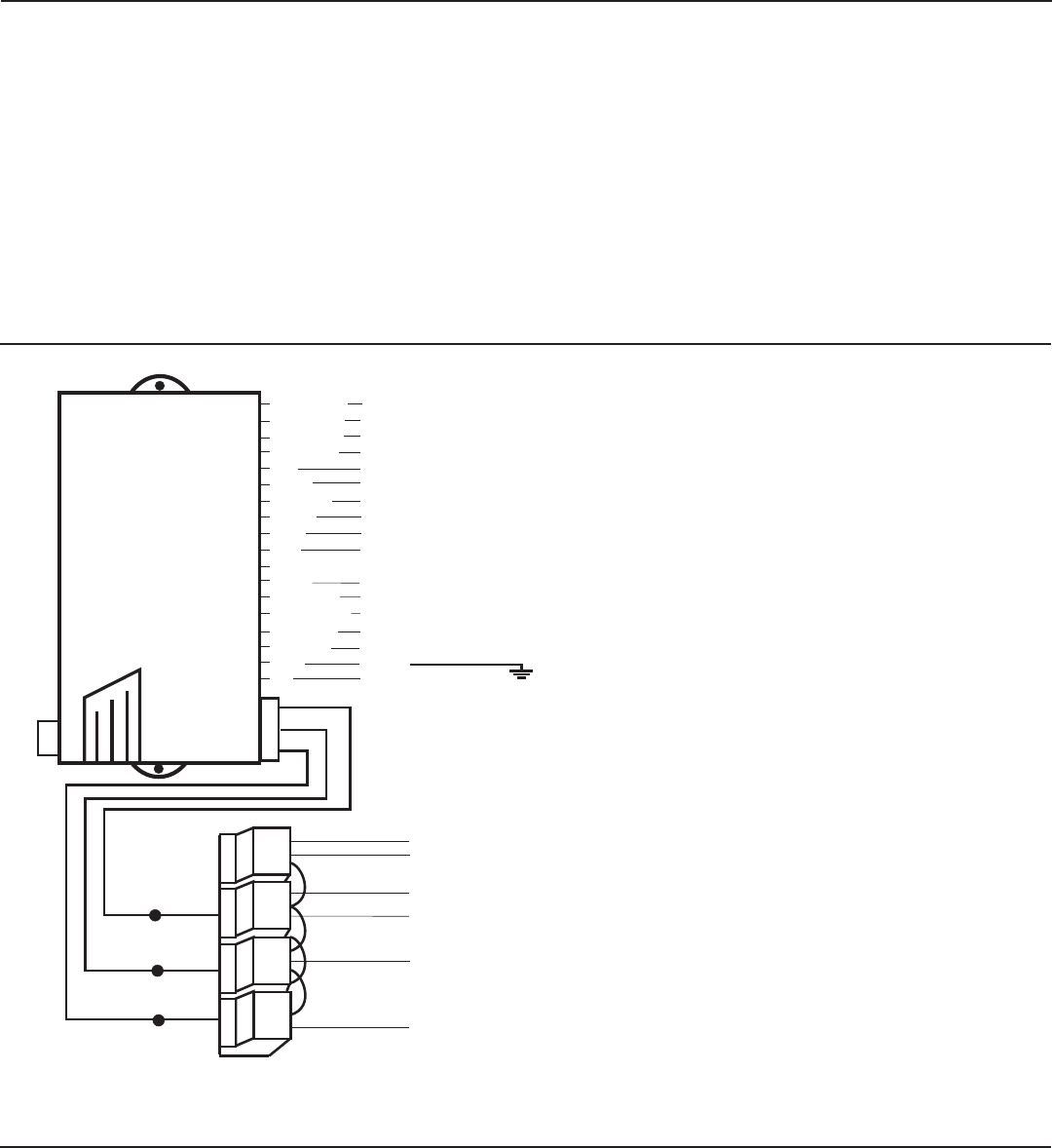
OPTIONAL CONNECTIONS
CAUTION: Before connecting the 18-pin
harness to the module, double check all
connections to be sure they are secure
and properly wrapped with electrical tape.
Make sure you mount the unit under the
driver’s side dash and secure the unit in
place with 2 wire ties. Make sure to
properly place the antenna, see antenna
placement, page 6. Next, plug the RED
antenna plug into the main control module.
Make sure you plug the 18-pin harness and
the 3-pin from the 4-relay harness into
the main module.
Press the start button, the parking lights
will flash once and the vehicle should
start and run. If your vehicle does not
start and run you may have a factory anti-
teft system. Refer to pages 7 to see if
this applies to your vehicle. If the
vehicle does start and run and you wish
at this time to install your door locks,
proceed to page 10.
BROWN/BLACK
GREEN/BLACK
BLACK/WHITE
BLACK/BLUE
BLUE
VIOLET
WHITE/RED
ORANGE
BROWN
GRAY
GRAY/BLACK
YELLOW
BLUE/BLACK
BLACK/YELLOW
GREEN
RED/BLACK
BLACK
RED
(-/+) Door lock output
(-/+) Door unlock output
Tach (-) to neg. side of coil
(-) To hood pin switch
(-) Auxiliary input
(-) Dome light supervision
(-) Trunk release
(-) Starter immobilizer output
(+) Parking lights
(+) Siren output
(-) Horn output
Ignition input
(+) Brake switch
(-/+) Positive/negative door pin input
(-) Shock sensor input
(-) Factory alarm shutdown
Ground
To +12V constant
WHT/BLK 16 ga.
WHITE 16 ga.
YEL/BLK 16 ga.
RED
2 Red wires need
+12V constant.
Either white wire to
Ignition 1. If your
car has 2 ignitions
use both.
To Starter/Crank
Wire
To Accessory Wire(s)
that run the
Heater/Blower Motor.
Attach at the ignition
switch wire harness
only.
RED
WHITE
WHITE
YELLOW/BLACK
WHITE/BLACK
Tap here when
installing bypass
module 721.
WHITE 16 ga
WHT/BLK 16 ga
YEL/BLK 16 ga
For Passlock I
For Passlock I
For Passlock II
ANTENNA
PLUG
750ma (-) Output
DOOR PIN TRIGGER
To determine if your door pin is turned on with (+) positive or (-) negative trigger, probe for a wire
in the driver’s side kick panel that switches polarity when the door is closed then opened. You can
also find this wire going to the under dash courtesy lights.
•If this wire reads +12V when the door is open and (-) ground when the door is closed, it is (+)
positive. (most Fords)
•If this wire reads (-) ground when the door is open and +12V when the door is closed, it is (-) negative.


