


6
Multiple Speaker Connections
Sometimes you may want to connect more than one speaker to a given channel of an amplifier. This can be done
with certain limitations. The main concern is that the impedance (or electrical “resistance”), expressed in ohms,
of the combined speaker load must be within a range common amplifiers can handle. The following information
describes basic common multi-speaker connection schemes. For the sake of clarity and space the connection
diagrams will show common schematic symbols.
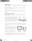
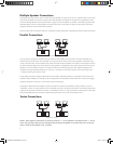
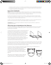
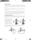
There are two basic connection methods - parallel and series. Examples of parallel connections are shown below.
The connection example on the left shows the wire from the amplifier and the wire for the second speaker con-
nected to the same terminals. The example on the right shows the wires to the second speaker connected to the
“loop” terminals which are connected to the other terminals inside the speaker. This makes connecting the wires to
the terminals easier. But it also means that if the first speaker is unplugged for any reason the signal to the second
speaker is cut off. Parallel connections can also be made by connecting wires from both speaker directly to the
amplifier terminals, typically referred to as “home run” connections. This often results in more wire being used
– usually something you want to avoid.
The parallel connection diagrams also show that two 8 ohm speakers produce an impedance of 4 ohms at the
amplifier. Most amplifiers can handle a 4 ohm impedance load. Impedance loads lower than 4 ohms can trigger
amplifier protection circuits or, in some cases, cause over heating.
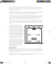
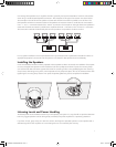
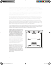
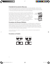
The diagram below shows examples of series connections. Two 8 ohm speakers in series produces a 16 ohm
impedance. This is an easy impedance for an amplifier to handle. However it will result in somewhat lower power
output. The connection method on the left is a modified “home run” type connection. The example on the right
side is electrically the same and often requires less wire. But it can be a bit more tricky to wire.
NOTE: These types of connections are unusual in that the “–” of one speaker is connected to the “+” of the
other. This may seem odd, but since the signal flows through one speaker to the other this is how it must be
done in order for the speaker to be “in phase”.
nÊÃ
""* ""*
nÊÃ
""* ""*
nÊÃ
""* ""*
nÊÃ
""* ""*
>«wiÀÊÀÊÀiViÛiÀ
£ÈÊà £ÈÊÃ
>«wiÀÊÀÊÀiViÛiÀ
{ÊÃ {ÊÃ
nÊÃ
""* ""*
nÊÃ
""* ""*
nÊÃ
""* ""*
nÊÃ
""* ""*
Parallel Connections
Series Connections
142-002648-D OWNERS MANUAL PRI.i6 6 10/4/07 3:26:41 PM