


5
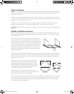
If the wire must be run more than 75 feet a high voltage distribution system is recommended. Such systems
use a special amplifier that has a “70V” (or in some countries, “100V”) output. This allows relatively small gauge
speaker wires to be run over great distances without signal degradation. Speakers used in a high voltage system
require a transformer. Special versions of the PRi series speakers with built-in transformers are available. Contact
a custom audio system installer for more information.
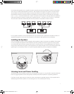
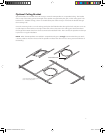
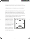
Connecting the Speakers
Unscrew the fasteners on the back of the speaker that hold the wire clamp in place. Open up the clamp and
insert about 2” of wire through the opening. Tighten the clamp screws to secure the wire. Note: If there is a
jacket around the two wire conductors fasten the clamp to the jacketed part of the wire. Remove the jacket from
the part of the wire that extends beyond the clamp.
Separate the two conductors of the wire. Remove about
3
⁄8” of insulation from the end of the wire. Insert the
wires into the appropriate terminals on the connector and tighten the screws on the top of the connector to
secure the wire. Be sure there are no loose strands of wire.
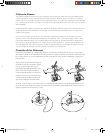
Just before the speaker is mounted plug the
connector into the back of the speaker. Set the
wire clamp in place and tighten the fasteners to
secure it. Finally pivot the moveable cover plate
into position and tighten its fastener to hold it
in place.
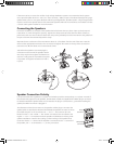
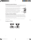
Speaker Connection Polarity
It is important that all the speakers in a system are hooked up with the same polarity or “in phase.” Instead of
the wire terminals typical of most speakers, the PRi series models are supplied with a Molex plug-in connector
to facilitate installation. Speaker wires are connected to the plug-in connector then, just before installing the
speaker, the Molex connector is plugged in.
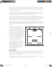
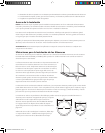
This illustration shows the connector on the speaker and the plug-in connector the
speaker wires are attached to. Note the label beside the speaker connector. It shows
the middle two pins on the connectors are “–” and “+”. The outer two pins are
labeled “LOOP +” and “LOOP –”. The “LOOP” connections are connected to the
regular “+” and “–” connections inside the speaker and facilitate connecting multi-
speaker installations. Use the color coding or other marking on the speaker wires
to be sure that the “+” terminal of the amplifier is connected to the “+” terminal of
the speaker, and “–” is connected to “–”, at every connection.
*,Ê-«i>iÀ
iVÌÀ
*Õ}
iVÌÀ
142-002648-D OWNERS MANUAL PRI.i5 5 10/4/07 3:26:40 PM