


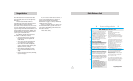
Bands
BandsDFT
In this setting, all North American radar and
laser frequencies are monitored. This is the
factory setting and it is recommended that
you use your V965 in this mode.
BandsMOD
In this setting, V965 will warn you with an
audible alert, and associated text message
stating which band has changed from the
original factory setting (i.e. “SWS ON”).
This warning is displayed during the start
up sequence (standard or fast).
16
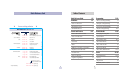
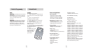
Details of Programming
Features and Specifications
Operating Bands
• X-band 10.525 GHz ±25 MHz
• K-band 24.150 GHz ±100 MHz
• Ka-band 34.700 GHz ± 1300 MHz
• Laser 904nm, 33 MHz bandwidth
Radar Receiver / Detector Type
• Superheterodyne, VTO
• Scanning Frequency Discriminator
• Digital Signal Processing (DSP)
Laser Detection
• Quantum Limited Video Receiver
• Multiple Laser Sensor Diodes
Display Type
• 280 LED Alphanumeric
• Bar Graph
• 3 Levels of Brightness, plus Dark Mode
Power Requirement
• 12VDC, Negative Ground
• Power cord (included)
Programmable Features
• Power-On Indication
• Voice Alerts
• Power-On Sequence
• AutoMute
• City Mode Sensitivity
• Bands
Sensitivity Control
• Highway, AutoScan and City
Auto Calibration Circuitry
VG2 Immunity
Dimensions (Inches)
• 1.25 H x 2.75 W x 4.75 L
Patented Technology
V965 is covered by one or more of the
following US patents.
6,614,385 6,587,068 6,400,305 6,249,218
6,069,580 5,668,554 5,600,132 5,587,916
5,559,508 5,365,055 5,347,120 5,446,923
5,402,087 5,305,007 5,206,500 5,164,729
5,134,406 5,111,207 5,079,553 5,049,885
5,049,884 4,961,074 4,954,828 4,952,937
4,952,936 4,939,521 4,896,855 4,887,753
4,862,175 4,750,215 4,686,499 4,631,542
4,630,054 4,625,210 4,613,989 4,604,529
4,583,057 4,581,769 4,571,593 4,313,216
D314,178 D313,365 D310,167 D308,837
D296,771 D288,418 D253,752
V965 is also covered by one or more of the
following Canadian patents:
1,295,715 1,295,714 1,187,602 1,187,586
Other patents pending. Additional patents
may be listed inside the product.
17
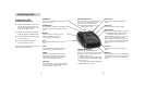
Technical Details
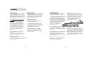
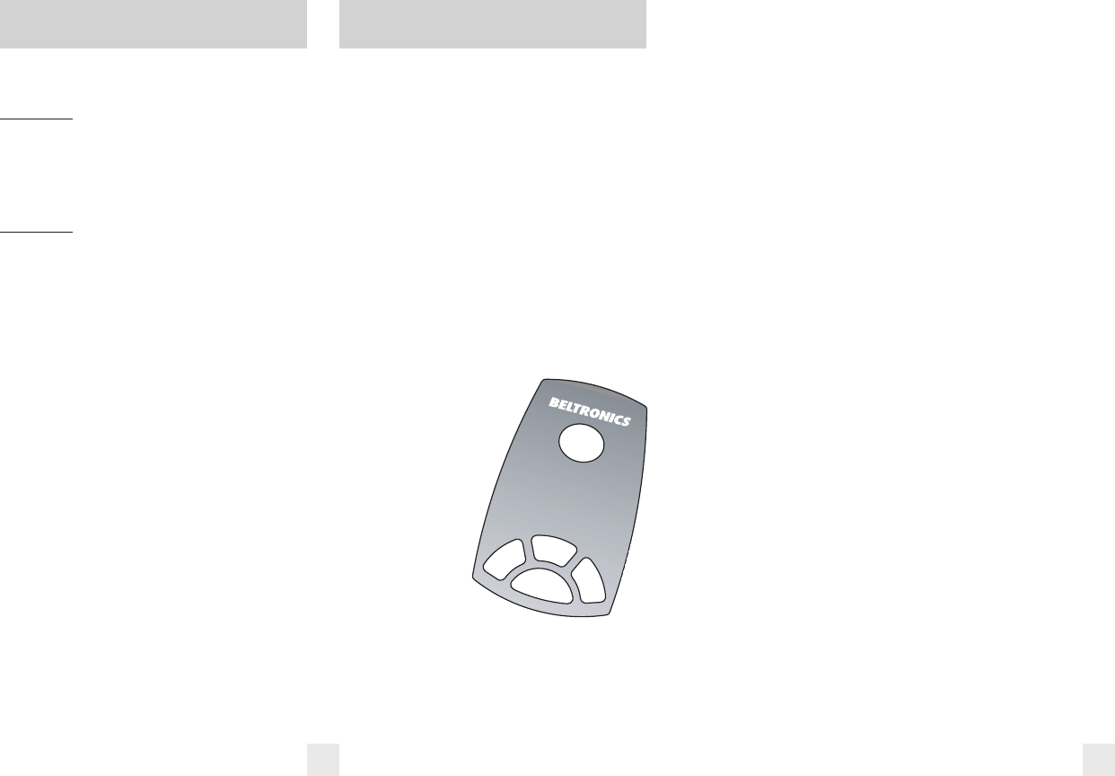
Faceplate
Removing the top faceplate
1 Using a sharp knife, or similar item, lift
one of the corners of the faceplate and pull
it off.
2 Remove any visible adhesive.
Installing the optional faceplate
1 Remove the backing from the button
area (lower half) first.
2 Align the optional faceplate over the
buttons first, and press down when it is
aligned correctly.
3 Once the button area of the faceplate is
pressed down, remove the remaining half of
the backing and press it
into place.
4 Press firmly around
the entire faceplate to
make certain the
adhesive has made
good contact.