


39
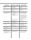
CONDITIONS
POSSIBLE CAUSES
CORRECTIONS
19. Potentiometer or CPS-2 output
decreases when it should
increase.
20. CPS-2 output nonlinear.
21. CPS-2 output does not reach
maximum signal, but low end
calibration is correct.
22. CPS-2 out of calibration.
23. CPS signal will not calibrate
down to 4 mA.
24. Control drive does not stay in
place with power off.
25. Control motor runs, but output
shaft does not move in one or
both directions.
26. Control drive equipped with
Modulating Option 5 or 6 and
an optional Relay Board does
not run reliably in one or both
directions in AUTO.
a. CPS-2 rotor position not set for
proper rotation.
b. End connections on
potentiometer reversed.
a. CPS-2 rotor position not set
properly.
b. CPS-2 zero potentiometer
misadjusted.
a. Output is overloaded—
• load resistance is too low for
voltage range.
• load resistance is too high for
current range.
b. Low voltage—
• CPS power supply failure.
c. CPS-2 rotor not set properly.
d. CPS-2 zero potentiometer
misadjusted.
a. CPS-2 zero potentiometer
inadvertently reset.
a. Not enough load on meter
circuit.
b. Unit being calibrated for shorter
than 80° rotation.
a. SLM friction surface worn.
a. SLM failure.
a. Controller output requires a
greater holding current than the
Relay Board load draws.
a. Reset CPS-2 rotor position. See
page 35.
b. See potentiometer calibration,
page 26.
a. Reset CPS-2 rotor position. See
page 35.
b. Refer to factory.
a. Check load resistance against
suggested feedback signal
terminal hook-up; see page 46.
b. Check line voltage at CPS-2
transformer terminals 1 and 3.
Check CPS-2 voltage at resistor.
Check CPS-2 power supply
voltage across capacitors C8 (13
V, except -05:15 V), C9 (15 V),
C10 and C11 (28 V).
c. Reset CPS-2 rotor position. See
page 35.
d. Refer to factory.
a. Refer to factory.
a. Connect 200 ohm resistor in
series with meter.
b. Remove R8. See Calibration
Procedure, page 27.
a. Replace SLM friction surface;
see page 34.
a. Replace control motor. See
page 33.
a. Check the controller output
required AC holding current. If
greater than 10 mA, additional
load must be provided.