


26
FEEDBACK SIGNAL
CALIBRATION
Feedback signal calibration is necessary to
ensure that signal current or voltage correctly
corresponds to the drive’s output shaft position.
All Group 14 drives are shipped with the feedback
calibrated for full retraction of the output shaft
unless otherwise specified at time of order.
The procedure to check and set feedback
calibration varies by model number. The model
number is listed on the drive name plate.
Determine the model number and refer to the
proper procedure below.
NOTE: The shaft travel limit switches must
be properly adjusted before the feedback
signal is calibrated. The feedback signal
must be calibrated before the input signal
can be calibrated.
Film Potentiometer Calibration
Models 14-_05 and 14-_07
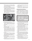
NOTE: On Model 14-_07 units equipped with
an auxiliary film potentiometer, the auxiliary
potentiometer is mounted closest to the
sector gear end of the control shaft.
When properly adjusted, the auxiliary potentio-
meter feedback signal should be maximum with
the drive shaft in the fully retracted (maximum
input signal) position. At 50% of travel, the signal
should be mid-span. At full extension, the signal
should be minimum.
On option 7 units, potentiometer feedback to
the ESR-4 board should read 0.54 V dc at the
minimum input signal position and 2.66 V dc at
the maximum input signal.
If either the auxiliary or main potentiometers
on option 7 units is out of calibration, or if the
feedback potentiometer on option 5 units is out
of calibration, the procedure to recalibrate is the
same:
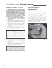
1. Open the terminal block cover (1/2” bolt
heads) and remove the top cover (15/16” bolt
head).
2. Loosen the clamping screw (use 9/64” hex
wrench) on the potentiometer wiper so that it
is just snug on the shaft.
3. Operate the drive to the electrical limit
corresponding to maximum input signal.
4. Set the wiper on the potentiometer so that the
voltage reaches its maximum value. Auxiliary
feedback signals are read by a multimeter at
CALIBRATION FEEDBACK SIGNAL
the terminal block (CC, DD, EE). Feedback
signals to the ESR-4 board are read on the
board at TP3 and TP2 (see Figure 11, page
31, for location).
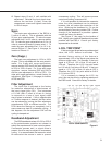
NOTE: Be sure that the wiper spans the
resistor and collector elements equally, and
does not touch the areas of low resistance at
either end of the film element.
5. Tighten the clamping screw to 5 Ib-in torque.
6. Operate drive between electrical limits. Verify
the feedback signal is properly adjusted.
7. Use the manual Handwheel to run the drive
to the mechanical limit; do not overtorque, as
damage may result.
8. Check that the wiper does not come off the
resistive element or output voltage does not
fall from maximum value. If not correct, return
to step 2.
9. Replace the top cover and close the terminal
block cover. Torque the terminal cover bolts
to 10 lb-ft. Tighten the top cover bolt just
enough to compress the O-ring seal.
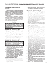
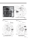
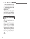
STANDARD FILM POT. CONNECTIONS FOR ESR