


13
CPS-2 SIGNAL CONNECTIONS
Beck Group 14 drives equipped with the
Contactless Position Sensor (CPS-2) are shipped
ready for installation. They are engineered to
match the mA or V dc feedback range in your
system.
Customer connections for feedback signal
wiring on each CPS-2 model are described in
the following diagrams and paragraphs. Refer to
Table 11, page 46, for output signal ranges, output
terminals, range changing resistance values, and
terminals to which the ranging resistor or jumper
is connected.
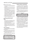
To verify that the feedback signal range
is correct for your drive, connect a mA / V dc
multimeter across the appropriate terminals
(check model number on CPS-2 transformer and
Table 11, page 46, for correct terminals CC, DD,
or EE). Use the Handswitch to operate the drive
throughout its full travel.
NOTE: Ranging resistors must be connected
to the control drive output terminals. If a
ranging resistor change is required, it may
be obtained locally. If resistors with ±1%
tolerance are not available, they can be
ordered from Beck.
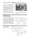
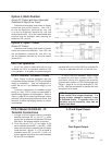
CPS-2 Model 20-3400-02, -12
Terminal Connections
1. A single 4–20 mA current output is available
between terminals EE (+) and CC (-) when
driving into an external load between 250 and
800 ohms. No ranging resistor is required.
2. For 4–20 mA and / or 1–5 V dc output, 4–20
mA is available across EE (+) and DD (-); 500
ohms is the maximum external load (for larger
loads see Item 1 above). A 1–5 V dc signal is
available across DD (+) and CC (-) into a 12
K ohm resistive load when the circuit between
EE and DD is completed.
4–20 mA Signal Output
Dual Signal Output
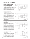
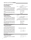
Option 3, Open / Close
Direct AC Control
Customer must supply three wires to directly
control the drive motor direction: One 120 V ac
line for Retraction (terminal M), one 120 V ac
line for Extension (terminal N), and one neutral
(terminal B).
240 V ac Operation
All of the options described above are
available for 240 V ac operation instead of 120
V ac operation. In all cases, the power neutral is
Option 4, Multi-Position
Direct AC Control with Cam-Operated
Switches to Stop Drive Travel
Customer must supply three wires to directly
control the drive motor direction: One 120 V
ac line for Retraction (terminal M), one 120
V ac line for Extension (terminal N), and one
neutral (terminal B). Up to five intermediate stop
positions may be specified, each requiring an
additional 120 V ac line.
replaced with Line 2 of the 240 V ac, and the 120
V ac line is replaced with Line 1 of the 240 V ac.