


Page 3
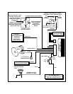
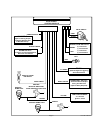
WIRING THE SYSTEM
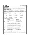
Large 8 Pin Edge Connector :
Red Fused Wire : + 12 VDC Constant Battery Source
This wire controls the sensitivity of the voltage sensing circuit, which detects the turning on of an interior light
when a door is opened. It will also detect the switching on of parking or headlamps, and in many cases will
trigger the alarm when a thermostatically controlled electronic radiator cooling fan switches on.
When installing this system into vehicles with electronic “ after fans “, it is recommended you disable the
voltage sense circuit.
In voltage sensing applications, the closer to the battery that the red wire is connected, the less sensitive
the voltage sense circuitry will be. Moving this connection point to the fuse panel will increase the sensitivity,
and connecting to the courtesy lamp fuse in the vehicle will provide maximum sensitivity of the voltage sense
circuit.
When hardwiring the control module to pin switches at all entry points, the voltage sense circuit must be
disabled. Move dip switch#2totheoffposition, then connect the red wire toa+12VDCconstant battery
source.
White Wire : + 12 VDC Pulsed Parking Light Output ( 15 Amp Max )
This wire is provided to flash the vehicle’s parking lights. Connect the white wire to the positive side of one of
the vehicle’s parking lights.
Black Wire : Chassis Ground
Connect this wire to a solid, metal part of the vehicle’s chassis. Do not confuse this wire with the thin black
antenna wire that exits the control module independently.
White w/ Black Trace Wire : Positive Output to Siren
Route this wire through a rubber grommet in the firewall, and to the siren location.
Connect the white / black wire to the positive wire of the siren. Secure the black ground wire of the siren to
chassis ground.
Dark Blue Wire : Delayed 300 mA Pulsed Output / Channel 2
The dark blue wire pulses to ground via an independent RF channel from the keychain transmitter. This is a
transistorized, low current output, and should only be used to drive an external relay coil.
WARNING: Connecting the dark blue wire to the high current switched output of trunk release circuits, some
remote start trigger inputs, will damage the control module.
Connect the dark blue wire to terminal 86 of the AS - 9256 relay ( or equivalent 30 A automotive relay ), and
wire the remaining relay contacts to perform the selected function of channel 2.
Dark Green w/ White Trace Wire : Entry Illumination ( 300 mA max. )
The dark green w/ white trace wire provides a 30 second ground signal whenever the system is disarmed,
and pulses ground whenever the system is triggered.
It should be used to provide the ( optional ) entry lighting, and to flash the vehicle’s dome light while the alarm
is sounding. This is a transistorized, low current output, and should only be used to drive an external relay
coil.
Connect the dark green with white trace wire to terminal 86 of the AS - 9256 relay ( or equivalent 30 A
automotive relay ), and wire the remaining relay contacts according to the polarity of the dome light circuit in
the vehicle.
NOTE : When wiring this feature in vehicles with factory equipped delay lighting circuits, it is best
to connect to the output of the timer which feeds the dome light, rather than at the door
switch. This will ensure that the dome light pulses when the alarm is triggered.