


128-8787
17 of 24
17
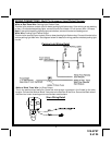
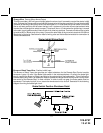
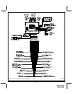
2 Pin Transponder Control Output: (Yellow Connector)
This output is intended to allow the control of a transponder bypass interface module or transponder
bypass relay. The system also allows software selections to control the way in which this output operates,
see remote start feature # 10 for setting this output.
When the unit is selected for output during the start sequence, this output will be active at the same time
Ign. 3 becomes active, and will remain active until the vehicle has started. This will be used for one time
read transponder circuits.
When the unit is selected for transponder on, this output will become active at the same time ign. 3
becomes active, and will remain active all the time the unit is operational under the control of the remote
start. When the unit is selected for continuous and the vehicle is started via the Remote Start, this output
will become active at the same time ign. 3 becomes active and will remain active until the ignition in the
vehicle goes low. This will allow the unit to be used for continuous read transponders circuits.
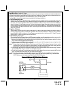
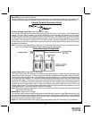
5 Wire Antenna/Receiver PB/LED Connector:
Plug the previously routed antenna connector from the antenna receiver assemble into the mating connector
of the control module. This connector supplies 12 volts, ground and RF data inputt, LED cathode, and Valet
Enable to and from the antenna receiver and the remote start module. Be certain this connector is firmly
seated making good contact to the control unit.
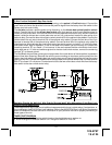
3 Pin Door Lock/Unlock Harness: (White Connector)
The Red and Green wires will provide either a pulsed ground output to the factory door lock control relay, or a
pulsed +12 volt output to the factory door lock control relay. In either case, the maximum current draw through
these outputs must not exceed 300 mA. The Red w/Black trace wire will provide a pulsed ground only, and will
only provide an output when the unlock button of the transmitter is pressed a second time after a first unlock
command was issued. This is used for second step unlock or all doors unlock in a two step circuit. In this
arrangement, Red is used to control the drivers door unlock relay, and the Red/Black will be used to control
unlock of all other doors.
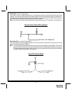
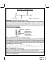
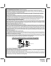
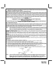
3 Wire Ground Switched Door Lock Circuits:
In this application, the Red wire of the door lock harness provides a ground pulse during the arming sequence,
or pulsed ground lock output. Connect the Red wire to the low current ground signal wire from the factory door
lock switch to the factory door lock relay.
The Green wire of the door lock harness provides a ground pulse during the disarming sequence, or pulsed
ground unlock output. Connect the Green wire to the low current ground signal wire from the factory door
unlock switch to the factory door unlock relay. See Below For Wiring Detail.
3 Wire Ground Switched Door Lock/Unlock Wiring Detail
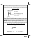
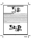
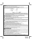
3 Wire Positive Switched Door Locks:
In this application, the Red wire of the door lock harness provides a +12 volt pulse during the disarming
sequence, or pulsed 12 volt unlock output. Connect the Red wire to the low current 12 volt signal wire from the
factory door unlock switch to the factory door unlock relay.
The Green wire of the door lock harness provides a +12 volt pulse during the arming sequence, or pulsed 12
volt lock output. Connect the Green wire to the low current 12 volt signal wire from the factory door lock switch
to the factory door lock relay. See Below For Wiring Detail.