


PROGRAMMING AND TESTING:
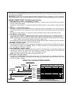
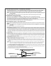
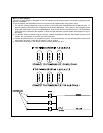
1. You will notice a 4 position dip switch on board the remote start module. Dip switch #1 and #2 are used to program
the Tach Rate. Refer to the chart below for proper setting of these dip switches.
2. Dip switch #3 controls the run time of the AS-9151N.
ON = 10 Minute Run Time
OFF = 15 Minute Run Time
3. Dip switch #4 controls the operation of the on board parking light flasher relay. This feature provides visual
confirmation whenever the vehicle is running under the control of the remote starter.
ON = Parking lights flash while the vehicle is running
OFF = Parking lights turn on steady while the vehicle is running
4. Test the System:
Press the appropriate button on the transmitter, that you have selected for the remote start operation. If the vehicle
did not start;
A. If the remote start did not activate in any way, check;
1. Is the control switch in the ON position.
2. Is there a solid connection on the Dark Blue remote input wire, and did the alarm send the ground signal
to this wire.
3. Verify that the fuses in the Red and Red w/ White tracer wires are not blown, and the connections onto the
fuseholders are adequate.
4. Verify that the Black wire is connected to a good, clean chassis ground source.
5. Check all inhibit circuits that have been connected, (i.e. is the hood opened, is the transmission in park,
are the brake lights on...etc.).
B. If the starter motor cranked, but engine did not start, check the connection and location of the Light Blue primary
ignition wire.
C. If the lights turned on, but the starter motor did not crank, check the connection and location of the Yellow
start wire.
COMPLETING THE INSTALLATION:
1. Mountthecontrol switch inthe passenger compartment,where it iseasily accessible tothe driver ofthe vehicle. Always
try to mount the switch so that the upward position is the ON or CLOSED position.
2. Mount the control module behind the dash using cable ties or sheet metal screws.
3. Securely tie all wiring up and away from all hot or moving parts of the vehicle. It is always recommended to use split
vinyl convoluted tubing along wire routing paths.
4. Apply the Caution label included in the kit to an area in the engine compartment that is clearly visible when the hood
is opened. Make sure the surface is clean before applying the label.
5. Replace all panels that were removed for installation ease, and re-test the system.
6. Explain all activated features of the remote starter to the customer.
SW #1
ON
ON
OFF
OFF
SW #2
OFF
ON
ON
OFF
CYLINDERS
4
6
8
12
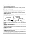
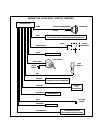
11.DARK GREEN Wire: Tach Sensor Input
This wire willcontinually monitorthe tach rate while the engine isrunning under power supplied by the Remote Starter.
Connect this wire to the existingtach wire, orthe negative side ofthe ignition coil inthe vehicle. (Seedip switch settings
below).