


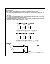

WIRING CONNECTIONS: 12 Pin Input / Output Harness
1. BLACK Wire: Chassis Ground Source
Connect this wire to a solid, clean chassis ground source.
2. DARK BLUE Wire: Remote Start Signal Input
Connect this wire to the pulsed ground output from the remote alarm system. In most cases, it will be connected to
the second or third channel output from the alarm. When the Dark Blue wire receives a ground pulse, the vehicle will
start.
3. BLACK w/WHITE Tracer Wire: Control Switch
The Black w/ White tracer wire provides ON-OFF control of the Remote Starter.
When the Black w/ Whitewire is switched to a full time ground, the AS-9151NRemote Start Module is operative. When
the Black w/ White wire is at open circuit through the control switch, the remote starter is disabled.
Connect the Black w/ White tracer wire to one of the terminals from the back of the control switch. Connect the
remaining terminal on the control switch to chassis ground. Always try to mount the switch so that the ON position
is in an upward direction.
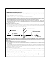
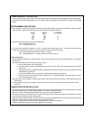
(2) IN4001
DIODES
GREY WIRE FROM REMOTE
START HARNESS
RED BUTT
CONNECTOR
FEMALE BULLET TERMINAL
DIODE BRIDGE ASSEMBLY
EXISTING HOOD PIN SWITCH
EXISTING ALARM
PIN SWITCH WIRE
MALE BULLET
4. GREY Wire: Negative Inhibit Input 1
Connect this wire to the existing hood pin switch from the alarm system, using the diode bridge included in the package.
Wire the diode bridge as shown in the illustration below. Any time the Grey wire is grounded, the Remote Starter will
stop operating, even if the signal is received from the alarm.
IMPORTANT ! If the alarm system does not incorporate a hood pin switch, you must add a switch to the Remote Start
system. This is an important safety feature of the AS-9151N Remote Starter, and failure to use this feature can result in
serious injury.
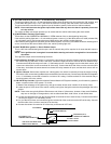
5. GREY w/ BLACK Tracer Wire: Negative Inhibit Input 2
Any time the grey w/ black tracer wire is grounded, the Remote Starter will stop operating, even if the signal is received
from the alarm.
If the brake light switch in the vehicle switches ground to the brake light circuit, connect the Grey w/ Black trace wire
to the output of the brake light switch. If the brake light switch in the vehicle switches +12 Volts, do not use the Grey
w/ Black wire; see Brown w/ White tracer wire.
6. BROWN Wire: Positive Inhibit Input 1
Any time + 12 Volts is applied to the Brown wire, the Remote Starter will stop operating, even if the signal is received
from the alarm.
If the vehicle has a factory installed hood pin switch, and that switch provides + 12 Volts to an under hood light, the
Brown wire can be connected to the existing pin switch.
7. BROWN w/ BLACK Tracer Wire: Positive Inhibit Input 2
Any time + 12 Volts isapplied to the Brown w/ Black tracer wire, the Remote Starter willstop operating, even if the signal
is received from the alarm. If the brake light switch in the vehicle switches + 12 Volts to the brake light circuit, connect
the Brown w/ Black trace wire to the output of the brake light switch. If the brake light switch in the vehicle switches
ground, do not use the Brown w/ Black wire; see Grey w/ Black tracer wire.