


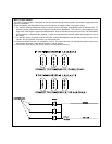
BATT 1
BATT 2
ACC
IGN 1
IGN 2
IGN 3
START
*
SPLICE(TYP.)
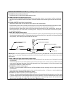
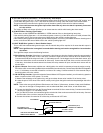
IGNITION SWITCH KEY POSITION
OFF ACCESSORY ON / RUN START
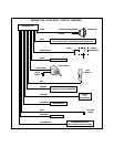
LT.BLUEWIRE
FROMAS-9151N
VIOLETWIRE
FROMAS-9151N
REDWIRE
FROMAS-9151N
REDw/WHITETRACE
WIREFROMAS-9151N
SEE"WIRINGTHE12PINCONNECTOR"-
LT.BLUEWIREIFREQUIRED.
LT.GREENWIRE
FROMAS-9151N
YELLOWWIRE
FROMAS-9151N
The AS-9151N is for Automatic Transmission vehicles only! Although it is a sophisticated system, with multiple built-in
safety features, it must not be installed into vehicles with manual transmissions. Doing this can cause serious personal
injury and property damage.
IMPORTANT ! DO NOT PLUG THE SIX PIN MAIN POWER HARNESS OR THE 12 PIN INPUT / OUTPUT HARNESS
INTO THEREMOTE STARTCONTROL MODULEUNTIL ALLCONNECTIONS HAVE BEENMADE TOTHE VEHICLE.
WIRING CONNECTIONS: 6 Pin Main Power Harness
1. RED w/ WHITE Tracer Wire:+12VDCBattery 1 Source
Connect this wire toa+12VDCconstant source. Using the 30 A fuse provided, connect this wire to the positive
terminal of the vehicle's battery.
The Battery 1 source provides + 12 volts to the AS-9151N module for Ignition 1 output, Ignition 2 output, and circuit
logic.
2.REDWire:+12VDCBattery 2 Source
Connect this wire toa+12VDCconstant source, but not the same source as the battery 1 wire, unless connecting
directly to the battery terminal. Using the 30 A fuse provided, connect this wire to the positive terminal of the vehicle's
battery.
The Battery 2 source provides + 12 volts to the AS-9151N module for Starter output and Accessory output.
3. YELLOW Wire : Starter Output
Connect this wire to the starter wire from the ignition switch harness. This wire will show +12 Volts when the ignition
key is turned to the “ START or CRANK “ position, and 0 Volts when the ignition key is in any other position.
NOTE: If installing the AS-9151N with an alarm that utilizes a starter cut relay,make sure the Yellow wire is connected
to the “ starter “ side of the relay contacts, and not the “ switch “ side.
When installing the AS-9151N into vehicles with a factory installed security system, connect the Yellow wire between
the output of the starter cut relay and the neutral safety switch.
4. BLUE Wire : Ignition 1 Output
Connect this wireto theignition 1 wire from the ignition switchharness. This wire will show +12 Volts when the ignition
key is turned to the “ RUN or ON “ and the “ START or CRANK “ positions, and 0 Volts when the key is turned to
the “ OFF “ and “ ACCESSORY “ positions.
5. LIGHT GREEN Wire : Ignition 2 Output
Connect this wire to the ignition 2 wire from the ignition switch. This wire will show +12 Volts when the ignition key
is turned to the “ RUN or ON “ position, and in some cases, the “ START or CRANK “ position. This wire will show
0 Volts when the key is turned to the “ OFF “ and “ ACCESSORY “ positions.
NOTE: Some older vehicles may not require the second ignition wire.
6. VIOLET Wire : Accessory Output
Connect this wire to the accessory wire from the ignition switch. This wire will show +12 Volts when the ignition key
is turned to the “ ACCESSORY “ and “ RUN or ON “ positions, and 0 Volts when the key is turned to the “ OFF “ and
“ START or CRANK “ positions.
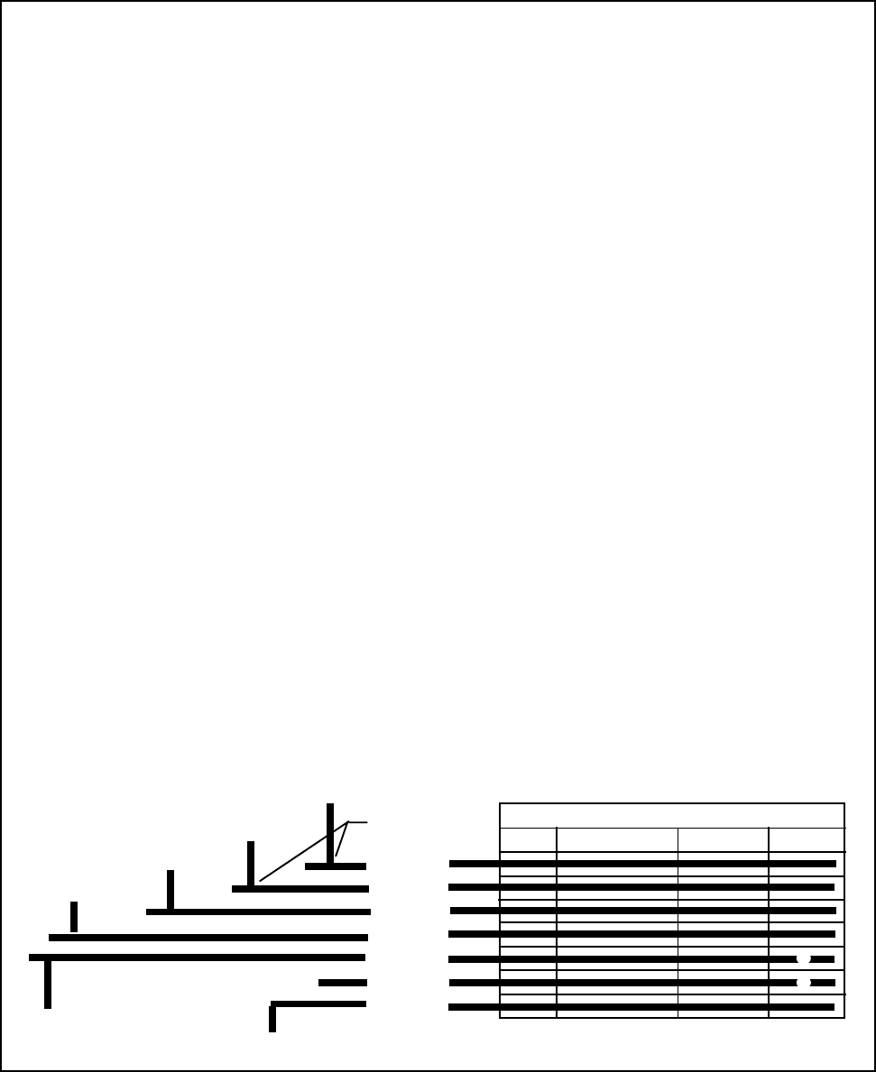
WIRING THE 6 PIN MAIN POWER HARNESS
MAY BE +12 VDC IN KEY POSITION INDICATED
+12 VDC IN KEY POSITION INDICATED
THIS CIRCUIT IS NOT ALWAYS REQUIRED FOR INSTALLATION
*