


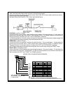
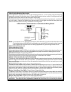
WIRING CONNECTIONS: 12 Pin Input / Output Harness
Black Wire: Chassis Ground Source
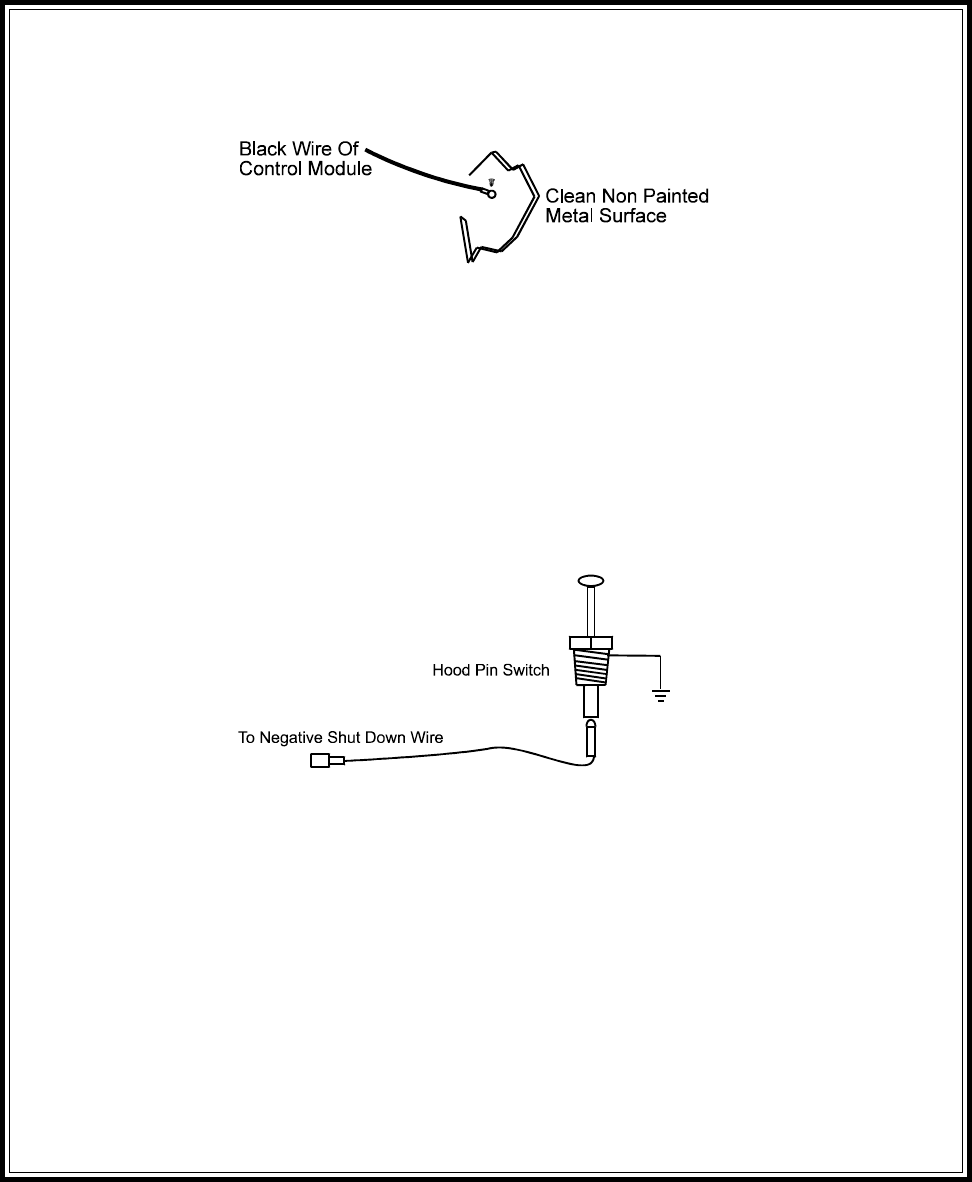
Connect the Black wire to a known vehicle ground source or to a solid clean metal part of the chassis. Be
certain to remove any paint or grease and secure this wire with a self taping screw and ring terminal.
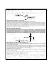
BLACK w/WHITE Tracer Wire: Control Switch
The Black w/ White tracer wire provides ON-OFF control of the Remote Starter.
When theBlack w/ Whitewire isswitched to afull time ground,the APS-675 RemoteStart Moduleis operative.
When the Black w/ White wire is at open circuit through the control switch, the remote starter is disabled.
Connect theBlack w/Whitetracer wireto oneof thewires fromthe backof thepreviously mountedcontrol switch.
Connect the remaining wire of the control switch to chassis ground. Always try to mount the switch so that
the ON position is in an upward or toward the driver direction.
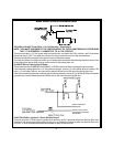
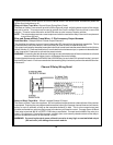
GREY Wire: Negative Inhibit Input 1
Connect theGREY wire to thepreviously mounted hood pinswitch provided . This wire willbe routed through
the fire wall into the engine compartment. It is necessary to use an existing grommet when passing wires
through the fire wall to prevent short circuiting. This is an important safety feature of APS 675, and failure to
use this feature can result in serious injury. Route the wire to the pin switch and connect it using the bullet
connector provided.
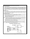
GREY w/ BLACK Tracer Wire: Negative Inhibit Input 2
Any time the grey w/ black tracer wire is grounded, the Remote Starter will stop operating, even if the signal
is received from the transmitter.
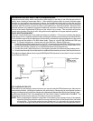
If the brake light switch in the vehicle switches ground to the brake light circuit, connect the Grey w/ Black
trace wire to the output of the brake light switch. If the brake light switch in the vehicle switches +12 Volts,
do not use the Grey w/ Black wire; see Brown w/ Black tracer wire.
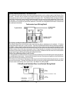
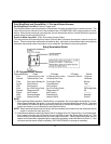
BROWN Wire: Positive Inhibit Input 1
Any time + 12 Volts is applied to the Brown wire, the Remote Starter will stop operating, even if the signal is
received from thetransmitter.
If thevehicle has a factoryinstalled hood pinswitch, and thatswitch provides + 1 2Volts to anunder hood light,
the Brown wire can be connected to the existing pin switch.
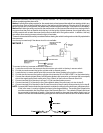
BROWN w/ BLACK Tracer Wire: Positive Inhibit Input 2
Any time + 12 Volts is applied to the Brown w/ Black tracer wire, the Remote Starter will stop operating, even
if the signal is received from the transmitter. If the brake light switch in the vehicle switches + 12 Volts to the
brake light circuit, connect the Brown w/ Black trace wire to the output of the brake light switch. If the brake
light switch in the vehicle switchesground, do not use the Brown w/ Black wire; seeGrey w/ Black tracer wire.
5