


Typically this output will be used to re-lock the vehicle doors if the doors unlock automatically when the
ignition circuit transitions to off.
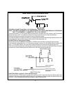
Black w/ Yellow Trace Wire: Ground Output During Start (Crank)
The Black w/ Yellow Trace wire will provide a 300 mA ground output while the starter output of the remote
start unit is active. This output can be used to activate the Crank Low/Bulb Test wire found in some GM
vehicles. This wire is also referred to as the ECM wake up wire in some Chrysler vehicles.
NOTE: The outputs above are low current outputs and must be used with a relay if the circuit's requirement
is more than 300 mA.
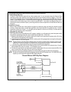
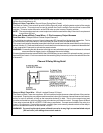
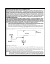
Blue and Green w/Black Trace Wires - 2 Pin Accessory Output Harness
Dark Blue Wire : Delayed 300 mA Pulsed Output/Channel 2
The dark blue wire pulses to ground via an independent RF channel from the keychain transmitter. This is
a transistorized, low current output, and should only be used to drive an external relay coil.
This outputis activatedby the sametransmitter buttonthat is usedto activatethe remote startfunction (factory
default is button 2). Press and hold button 2 to activate this trunkrelease output, or press and release button
2 two times within 2 seconds to activate the remote starter.
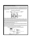
WARNING: Connecting the darkblue wire tothe high currentswitched output ofthe trunk releasecircuits and
some remote start trigger inputs, will damage the control module.
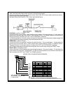
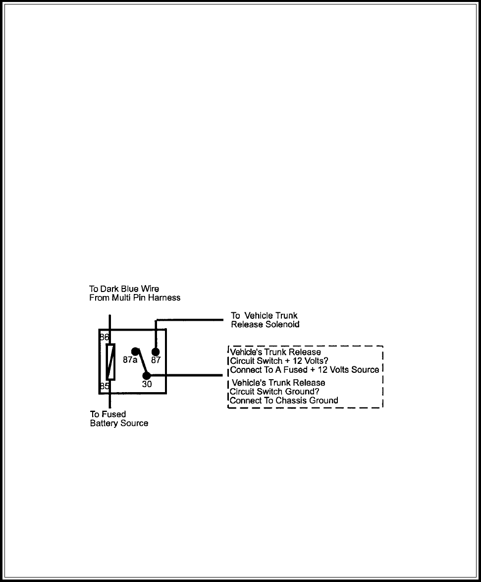
Connect thedark blue wire toterminal 86 ofthe AS-9256 relay(or equivalent 30 Aautomotive relay), connect
terminal 85 to a fused +12 volt source and wire the remaining relay contacts to perform the selected function
of channel 2.
Channel 2 Relay Wiring Detail
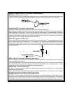
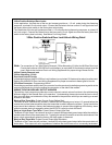
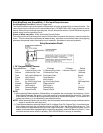
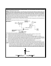
Green w/ Black Trace Wire: 300mA Latched Channel 3 Output
The Green w/ Black Trace wire supplies a 300 mA switched output whenever channel three of the receiver
is accessed. Pressing the pre-programmed transmitter button(s) will access channel three and will remain
active, for up to 8 seconds, as long as the transmitter button(s) is held. This is a low current output and
must be connected to a relay to supply power to the device you intend to control. Connect Green w/ Black
Trace wire to terminal #86 of a VF45F11 P&B relay or equivalent. Connect terminal #85 of the relay to a
fused + 12 volt source. Connect the common, normally open, and normally closed contacts of the relay to
perform the selected function of the channel 3 output.
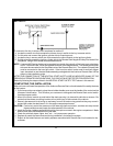
WARNING ! Connecting the dark green w/black trace wire to any high current switched output
(300 mA max.) will damage the control module.
10