


2 Pin Red Connector : HI-JACK OVERRIDE
Route the 2 pin red connector from the override switch previously mounted to the mating two pin
connector on the module.
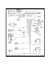
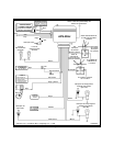
Red & Green 2 Pin White Connector : DOOR LOCK OUTPUTS
These wires will provide a pulsed ground output to the factory door lock control relay. The maximum
current draw through these outputs must not exceed 300 mA.
3 Wire Ground Switched Door Locks
In this application, the red wire provides a ground pulse during arming, or the pulsed ground lock
output. Connect the red wire to the wire that provides a low current ground signal from the factory door
lock switch to the factory door lock control relay.
The green wire provides a ground pulse during disarming, or the pulsed ground unlock output.
Connect the green wire to the wire that provides a low current ground signal from the factory door
unlock switch to the factory door lock control relay.
3 Wire Positive Switched Door Locks
4 Wire Polarity Reversal and
5 Wire Alternating 12 Volt
Door Lock Control Circuits
In these applications, the AS 9159 Door Lock Interface ( or equivalent 30 A automotive relays ) must be
used. Refer to the AUDIOVOX Door Lock Wiring Supplement for proper connection to these types of
circuits.
COMPLETING THE INSTALLATION
Antenna Wire : Be sure to extend the thin black antenna wire to it’s full length, and cable tie into place
where it cannot be damaged. Avoid wrapping this wire around major, high current wire looms.
Adjusting the Shock Sensor :
Using a small screwdriver, gently turn the adjustment screw fully counterclockwise. ( DO NOT over turn
this screw. Maximum rotation for this adjustment is 270° ). Close the hood and trunk lids, and arm the
alarm. Wait 6 seconds for the accessories trigger zone to stabilize, then firmly strike the rear bumper
with the side of a closed fist considering the amount of force required to break a window.
CAUTION : Never perform this test on the vehicle’s glass, as you may break the window.
Turn the adjustment screw clockwise ( increasing sensitivity ) about ¼ turn and re - test. Repeat this
procedure until the alarm sounds. Ultimately, one firm strike to the rear bumper will cause the alarm to
trigger.
WARNING ! Setting the sensitivity too high can cause false alarms due to noise vibrations from passing
trucks and heavy equipment. To decrease sensitivity, turn the adjustment screw counter
clockwise.
Wire Dressing : Always wrap the alarm wires in convoluted tubing, or with a spiral wrap of electrical
tape. Secure these looms along the routing using cable ties. This will ensure that the alarm wires are not
damaged by falling onto hot or sharp moving surfaces in the vehicle.
Operation : Take a few moments to check off the appropriate option boxes in the owner’s manual, and
to fully explain the operation of the system to your customer.
Page 5