


Black Wire : CHASSIS GROUND
Connect this wire to a solid, metal part of the vehicle’s chassis. Do not confuse this wire with the thin
black antenna wire that exits the control module independently.
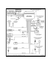
Orange Wire: 300 mA GROUND OUTPUT WHEN ARMED - N. C. STARTER DISABLE (Optional
Relay Required)
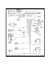
This wire is provided to control the starter cut relay. Connect the orange wire to terminal 86 of the relay.
Connect relay terminal 85 to an ignition wire in the vehicle that is live when the key is in the on and
crank positions, and off when the key is in the off position. ( This is where the yellow wire from the alarm
should be connected ).
Cut the low current starter solenoid wire in the vehicle, and connect one side of the cut wire to relay
terminal 87A. Connect the other side of the cut wire to relay terminal 30.
Note : This is a normally closed starter cut arrangement, and when power is removed from the
security system, the starter disable feature will not operate, allowing the vehicle to start.
Audiovox does not recommend using the Orange wire to interrupt anything but the
starting circuit of the vehicle.
Brown Wire : - DOOR TRIGGER
If the vehicle’s courtesy light switches havea(-)ground output when the door is opened ( GM and most
Imports ), you must connect this wire to the negative output from one of the door switches.
WARNING : Do not use the brown wire if the vehicle has + 12 volt output type door switches.
( see Purple Wire ).
Dark Green Wire : ( - ) Instant Trigger Zone 2
This is an instant on ground trigger wire. It must be connected to the previously installed hood and trunk
pin switches.
Yellow w/ White Trace Wire : 300 mA GROUND OUTPUT DURING HI-JACK ACTIVE STATE
(Optional Relay Required ).
This wire provides a progressive output to control a relay which in turn will control the vehicle shut down
circuit (Ignition or Fuel) during the Hi-Jack triggered mode. Connect the Yellow/White trace wire to
terminal 86 of a relay. Connect relay terminal 85 to an ignition wire in the vehicle that is live when the
key is in the on and crank positions, and off when the key is in the off position. ( This is where the yellow
wire from the alarm should be connected ).
Cut the ignition or electric fuel pump feed wire at a convenient location in the vehicle. Connect one side
of the cut wire to relay terminal 87. Connect the other side of the cut wire to relay terminal 30.
Note : This is a normally opened ignition/electric fuel pump inhibit arrangement. When power
is removed from the security system, the inhibit feature will remain operational, and the
vehicle will not start or will not continue to run. Audiovox recommends redundant test-
ing of your connections to the vehicle concerning this circuit as a poor connection will
prevent the vehicle from starting.
2 Pin Blue Connector : VALET SWITCH
Route the grey and black wires in the 2 pin connector from the valet switch to the control module, and
plug it into the mating blue connector on the side of the module.
2 Pin White Connector : DASH MOUNTED L.E.D.
Route the red and blue wires in the 2 pin white connector from the L.E.D. to the control module, and
plug it into the mating white connector on the side of the module.
Page 4