


128-8613
8 of 12
Page 8
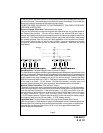
3 Pin Antenna/Receiver, Connector “F”
Route the 3 pin connector from the previously installed antenna receiver assemble to the
mating connector on the control module. This connector supplies 5 volts, ground and RF
data from the antenna receiver to the remote start module. Be certain this connector is
firmly seated making good contact to the control unit.
2 Pin LED Harness, Connector “G”
Route the twin lead Red and Blue wires from the LED to the remote start control unit and
plug the two pin connector into the mating white mini connector on the control module.
these wires control the anode and cathode of the dash mounted LED.
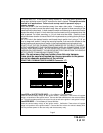
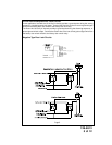
3 Pin Parking Light Input/Output & Ground Harness, Connector “H”
Black Wire: Chassis Ground Source
Connect the Black wire to a known vehicle ground source or to a solid clean metal part of
the chassis. Be certain to remove any paint or grease and secure this wire with a self
tapping screw and ring terminal.
White w/ Red Trace Wire: Parking Light Flasher Feed
This wire is the common contact of the on board parking light flasher relay. If the vehicle
you are working on has +12 volt switched parking lights, connect this wire to a fused + 12
volt source. (Max. 15 Amps)
NOTE: If the vehicle's parking lights are ground switched, connect this wire to chassis
ground.
White Wire: Parking Light Flasher Output
This wire is the normally open contact of the on board parking light flasher relay. Connect
this wire to the vehicle parking light feed wire.
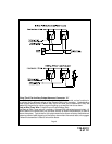
7 Pin Accessory Input/Output Harness, Connector “E”
Brown w/ Black Trace Wire: Positive Inhibit Input
The Brown w/ Black Trace wire provides an instant shutdown for the Remote Start Control
module whenever it gets + 12 volts. If the Brake lights switch in the vehicle switches + 12
volts to the brake light circuit, connect the Brown w/ Black trace wire to the output side of
the brake switch. This will allow the Remote Start to shut down if an attempt is made to
operate the vehicle without the key while running under the control of the Remote Start. In
most vehicles, in order to shift into gear, the brake pedal must be depressed. The brake
input will in turn cause the remote start unit to shut off.
Grey w/ Black Trace Wire: Negative Inhibit Input
The Grey w/ Black Trace wire provides an instant shutdown for the Remote Start Control
Module whenever it is grounded. Connect the Grey w/ Black trace wire to the hood pin
switch previously installed. This wire must be routed through a grommet in the firewall
and connected to the hood pin switch. If the pin switch is to be used with an alarm
system, connect this wire using a diode assembly.
DO NOT RELEASE THIS VEHICLE TO THE CONSUMER UNTIL YOU CONFIRM THE
OPERATION OF THE HOOD PIN SAFETY SHUT DOWN FEATURE.
IMPORTANT! This connection is a safety wire and must be connected to a hood pin
switch and tested as described. Failure to do so may result in personal injury or property
damage. This wire may also be used if the vehicle brake light circuit switches ground to
the brake lights. An isolation diode must be used for ground switched brake light circuits
and must be connected to the output of the brake switch.