


128-8613
4 of 12
Page 4
YELLOW Wire: Starter Output
Careful consideration for the connection of this wire must be made to prevent the
vehicle from starting while in gear. Understanding the difference between a me-
chanical and an electrical Neutral Start Switch will allow you to properly identify
the circuit and select the correct installation method. In addition you will realize
why the connection of the safety wire is required for all mechanical switch con-
figurations.
Failure to make this connection properly can result in personal injury and property damage.
In all installations it is the responsibility of the installing technician to test the remote start
unit and ensure that the vehicle cannot start via RF control in any gear selection other than
park or neutral.
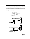
In both mechanical and electrical neutral start switch configurations, the connection of the
Yellow wire will be made to the low current start solenoid wire of the ignition switch harness.
This wire will have +12 volts when the ignition switch is turned to the start (crank) position
only. This wire will have 0 volts in all other ignition switch positions.
BLUE Wire: Ignition 1 Output
Connect this wire to the ignition 1 wire from the ignition switch. This wire will show +12 volts
when the ignition key is turned to the "ON" or "RUN" and the "START" or CRANK"
positions, and will have 0 volts when the key is turned to the "OFF" and "ACCESSORY"
positions.
GREEN Wire: Ignition 2 Output
Connect this wire to the ignition 2 wire from the ignition switch. This wire will show + 12
volts when the ignition key is turned to the "ON" or "RUN" position and is some cases the
"START" or CRANK" position. This wire will show 0 volts when the key is turned to the
"OFF" and "ACCESSORY" positions.
NOTE: See programming information (Bank 3 Selection # 6) concerning this wire to allow
output during the "START" mode.
VIOLET Wire: Accessory Output
Connect this wire to the Accessory wire from the ignition switch. This wire will show + 12
volts when the ignition switch is turned to the "ACCESSORY" or "ON" and "RUN" posi-
tions, and will show 0 volts when the key is turned to the "OFF" and "START" or "CRANK"
positions.
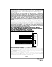
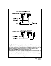
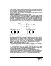
Wiring The 2 Pin Door Lock/Unlock Harness Connector “B”:
The Red & Green Door Lock/Unlock output wires provide a pulsed ground output to control the
vehicle door lock / unlock circuits. The output of these wires has a maximum switching capability
of 250 mA. Many vehicles today have factory door lock relays which can be connected directly to
these outputs, however always confirm that the factory relays in your particular vehicle do not
exceed the rated 250mA output of the units door lock/unlock circuit. Plug the 2 pin connector of the
door lock/unlock harness into the mating connector shell of the control module. Determine the
door lock circuit of the vehicle you are working on and wire according to the diagrams shown.