


128-8210
5 of 16
5
NOTE: See programming information concerning this wire to allow output during the "START" mode.
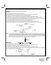
VIOLET WIRE: Accessory Output
Connect this wire to the Accessory wire from the ignition switch. This wire will show + 12 volts when the ignition
switch is turned to the "ACCESSORY" or "ON" and "RUN" positions and will show 0 volts when the key is turned to the
"OFF" and "START" or "CRANK" positions.
WIRING CONNECTIONS: 12 Pin Input / Output Harness
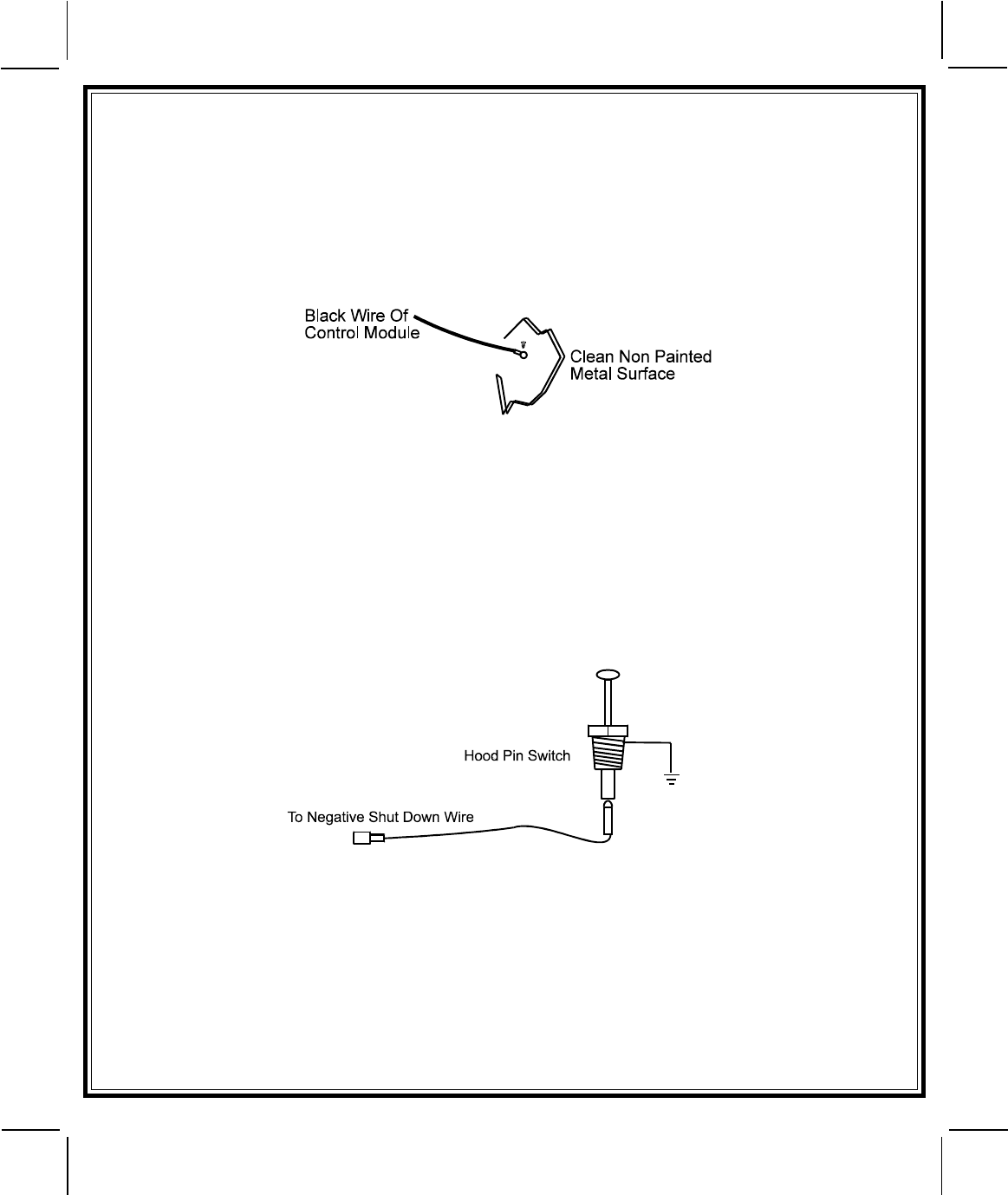
Black Wire: Chassis Ground Source
Connect the Black wire to a known vehicle ground source or to a solid clean metal part of the chassis. Be certain to
remove any paint or grease and secure this wire with a self-tapping screw and ring terminal.
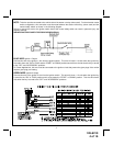
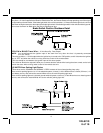
BLACK w/WHITE TRACER WIRE: Control Switch
The Black w/ White tracer wire provides ON-OFF control of the Remote Starter.
When the Black w/ White wire is switched to a full time ground, the Remote Start Module is operative. When the Black
w/ White wire is at open circuit through the control switch, the remote starter is disabled.
Connect the Black w/ White tracer wire to one of the wires from the back of the previously mounted control switch. Connect
the remaining wire of the control switch to chassis ground. Always try to mount the switch so that the ON position is
in an upward or toward the driver direction.
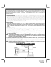
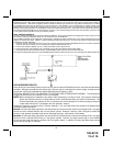
GRAY WIRE: Negative Inhibit Input 1
Connect the GRAY wire to the previously mounted hood pin switch provided. This wire will be routed through the firewall
into the engine compartment. It is necessary to use an existing grommet when passing wires through the firewall to
prevent short circuiting. This is an important safety feature of the System, failure to use this feature can result in serious
injury. Route the wire to the pin switch and connect it using the bullet connector provided.
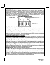
GRAY w/ BLACK TRACER WIRE: Negative Inhibit Input 2
Any time the gray w/ black tracer wire is grounded, the Remote Starter will stop operating, even if the signal is received
from the transmitter.
If the brake light switch in the vehicle switches ground to the brake light circuit, connect the Gray w/ Black trace wire
to the output of the brake light switch. If the brake light switch in the vehicle switches +12 Volts, do not use the Gray
w/ Black wire; see Brown w/ Black tracer wire.
BROWN WIRE: Positive Inhibit Input 1
Any time + 12 Volts is applied to the Brown wire, the Remote Starter will stop operating, even if the signal is received
from the transmitter.
If the vehicle has a factory installed hood pin switch and that switch provides + 12 Volts to an under hood light, the Brown
wire can be connected to the existing pin switch.