


128-8210
6 of 16
6
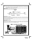
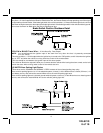
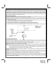
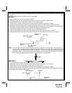
BROWN w/ BLACK Tracer Wire: Positive Inhibit Input 2
Any time + 12 Volts is applied to the Brown w/ Black tracer wire, the Remote Starter will stop operating, even if the signal
is received from the transmitter. If the brake light switch in the vehicle switches + 12 Volts to the brake light circuit, connect
the Brown w/ Black trace wire to the output of the brake light switch. If the brake light switch in the vehicle switches ground,
do not use the Brown w/ Black wire; see Gray w/ Black tracer wire.
Brake Switch Positive Shutdown Detail
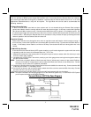
YELLOW w/ BLACK Tracer Wire: + 12 Volt Alarm By - Pass Output
NOTE: You must disconnect the ignition input of the alarm from any other wire that it is presently connected
to in the vehicle.
This wire provides a + 12 Volt output when the ignition key is turned to the “ON” position, and 0 Volts when the ignition
key is “OFF” and when the vehicle is running under the control of the remote starter.
This wire should be connected to the ignition input of the alarm system.
The Yellow w/ Black wire output will allow you to remote start the vehicle while leaving the alarm armed, and to lock/
unlock the doors while running under control of the remote start unit.
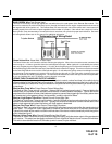
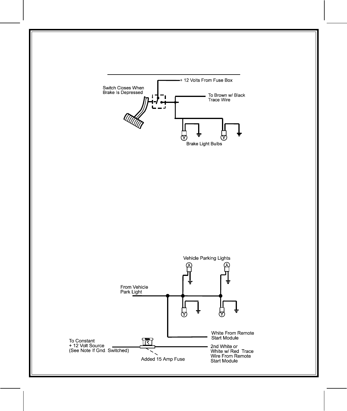
(2) WHITE Wires: Parking Light Flasher
These wires are the COMMON and NORMALLY OPEN contacts of the on-board parking lamp relay.
If the vehicle's parking lights are a +12 volt switched system, connect (1) of the White wires to a fused (15A max.) +12
volt battery source, and connect the second White wire to the vehicle's parking light wire.
If the vehicle's parking lights are a chassis ground switched system, connect (1) of the White wires to a chassis ground
source, and connect the second White wire to the vehicle's parking light wire.
Switch