


128-8210
3 of 16
3
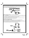
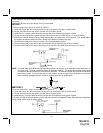
THE RECEIVER/ANTENNA ASSEMBLY:
The Superheterodyne Receiver Antenna Assembly provided with this unit allows routing from below the dashboard
for maximum operating range. Choose a location above the belt line (dashboard) of the vehicle for best reception.
Special considerations must be made for windshield glass as some newer vehicles utilize a metallic shielded
window glass that will inhibit or restrict RF reception. In these vehicles, route the antenna toward a rear window
location for best reception. Secure the antenna with double stick tape provided. After securing the antenna with tape,
we advise also securing a section of the antenna cable to a fixed support. This will prevent the antenna from
dropping down in case the double stick tape is exposed to extreme heat, which may loosen its gummed surface.
Route the 3 pin connector toward the control module using caution not to pinch the cable as this will cause poor or
no RF reception to the control module.
IMPORTANT!
DO NOT PLUG THE SIX PIN MAIN POWER HARNESS OR THE MULTI PIN INPUT / OUTPUT HARNESS INTO THE
CONTROL MODULE UNTIL ALL CONNECTIONS TO THE VEHICLE HAVE BEEN MADE. AFTER SELECTING YOUR
TARGET WIRES AS DEFINED BELOW, DISCONNECT THE NEGATIVE BATTERY CABLE FROM THE VEHICLE BAT-
TERY PRIOR TO MAKING ANY CONNECTIONS.
Note: Do not remove the fuse holders from this wire harness. Fuses must be
used and located as close as possible to the power source for adequate protec-
tion of the vehicle.
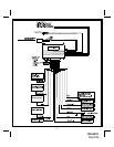
WIRING THE 6 PIN MAIN POWER HARNESS:
Fused RED w/ WHITE TRACE WIRE: + 12 volt Battery 1 Source
Locate the vehicle battery wire(s) at the ignition switch. Verification: These wires will register voltage in all positions
of the ignition switch. Connect the Red w/White wire to the vehicle's battery wire. This wire provides power for the
control circuit as well as the ignition 1 and ignition 2 relays.
Fused RED WIRE: + 12 Volt Battery 2 Source
Locate the vehicle battery wire(s) at the ignition switch. Verification: These wires will register voltage in all positions
of the ignition switch. Connect the Red wire to the vehicle's battery wire. This wire provides power for the start relay
and the accessory relay.
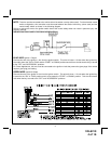
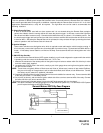
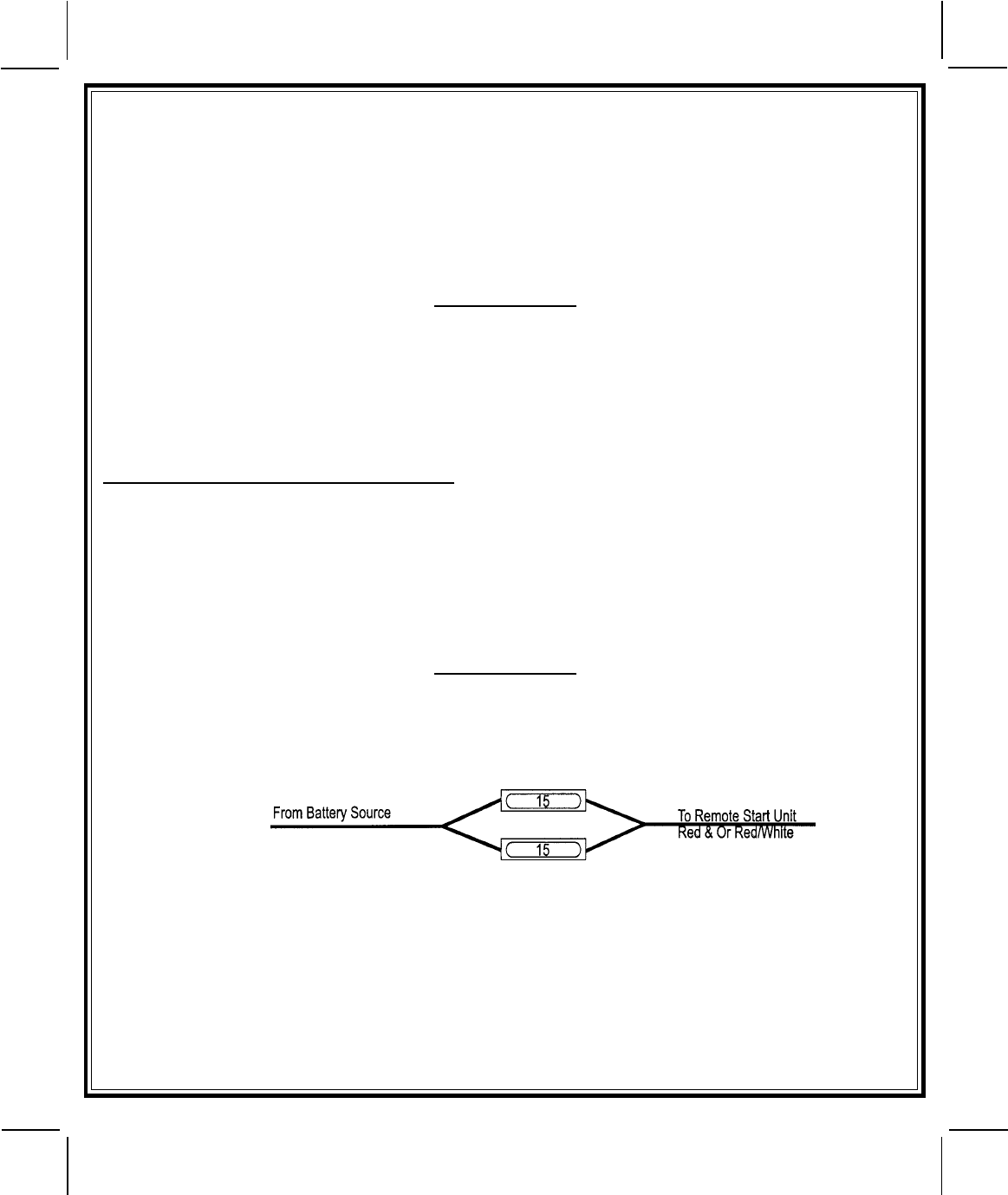
IMPORTANT!
IT IS THE RESPONSIBILITY OF THE INSTALLING TECHNICIAN TO DETERMINE THE LOAD FACTOR OF THE
VEHICLES ELECTRICAL CIRCUITS WHEN THE VEHICLE IS RUNNING AND TO ADEQUATELY FUSE THE TWO
POWER WIRES BASED ON THAT LOAD. IF THE VEHICLE, RUNNING UNDER LOAD WITH THE AIR CONDITIONER,
HEATER BLOWER MOTOR, AND ACCESSORIES EXCEEDS 24 AMPS CONTINUOUS, WE RECOMMEND THAT TWO
FUSES BE USED IN COMBINATION ON EACH POWER WIRE AS SHOWN BELOW. FOR ADDITIONAL INFORMATION
SEE TECH UPDATE ISSUED 9/30/96.
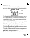
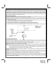
YELLOW WIRE: Starter Output
Careful consideration for the connection of this wire must be made to prevent the vehicle from starting while in
gear. Understanding the difference between a mechanical and an electrical Neutral Start Switch will allow you
to properly identify the circuit and select the correct installation method. In addition you will realize why the
connection of the safety wire is required for all mechanical switch configurations.
Failure to make this connection properly can result in personal injury and property damage. In all installations it is the
responsibility of the installing technician to test the remote start unit and assure that the vehicle cannot start via RF
control in any gear selection other than park or neutral.
In both mechanical and electrical neutral start switch configurations, the connection of the Yellow wire will be made
to the low current start solenoid wire of the ignition switch harness. This wire will have +12 volts when the ignition
switch is turned to the start (crank) position only. This wire will have 0 volts in all other ignition switch positions.