


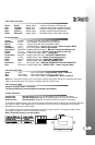

3250 Wiring Diagram Page 3
Pre-Installation Page 4
Components
Pre Installation Check
Installation Procedure
Wire Connectors Page 5
6 Pin Connector
14 Pin Connector
4 Pin Red Connector
2 Pin White Connector
Jumper Selection
Installation Page 6
Basic Installation - Quick start
Auto Tach Learn
Programming Page 7-9
Program Overview & System Reset
Program Menu 1 (User Settings)
Program Menu 3 (Starter Settings)
Program Menu 4 (Tach Settings)
Operations Page 10
Transmitter Operation
Timer Mode Settings
Reservation Mode ( Manual Transmission Only)
Additional Operations Page 11
Transmitter Programming
Service Mode (Valet Mode)
Relay Diagrams Page 12
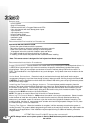
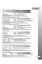
If the remote starter has a failed start attempt or if a safety input is activated the Diagnostic Memory will store
up to four shutdowns in memory. This information can then be accessed to determine the source of the
shutdown.
To Enter Diagnostic Mode:
Step 1 - Turn the ignition on wait two seconds then turn off. Press the Program Button and release.
Step 2 - The system will respond with three park light flashes and the horn will honk (optional) the
same number of times as the events in memory. ( Maximum four events, four honks)
NOTE: If the horn does not honk, there are no events in memory.
Step 3 - Press the Program Button once to view the last shut down code. The (optional) Horn will honk once
to confirm code one. (If the horn does not honk, there are no codes in memory).
Step 4 - The LED’s on the antenna will flash a code corresponding to a shut down trigger. Press the
Program Button again to check the second code. The horn will honk twice to confirm code two.
Step 5 - To Clear Diagnostic Memory. While in Diagnostic Mode press and hold the Program Button for five
seconds. The park lights will flash and the horn(optional) will honk once.
NOTE: Once diagnostic memory has 4 shutdown events in memory, the system will not record
Any further shutdown events until the system memory has been cleared.
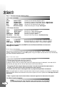
PARK LIGHTS STATUS LED DIAGNOSTIC CODE
3 Flashes Series of 3 Flashes Door Opened “M” Models
3 Slow Flashes No Flashes Start Attempt In Service Mode
4 Slow Flashes Series of 4 Flashes Not in Reservation Mode “M” units
4 Flashes Series of 4 Flashes Hood Pin Grounded (Open)
6 Flashes Series of 6 Flashes Brake Pedal Shutdown
7 Flashes Series of 7 Flashes Tach Lock-Out
8 Flashes Series of 8 Flashes 3 Start Attempts with no start
DIAGNOSTICS
2
3
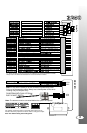
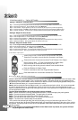
FM ANTENNA WITH DUAL LED’S AND
BUILT-IN VALET SWITCH
11
55
33
22
44
66
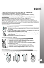
Access To
Jumpers
**** These connection’s are only necessary for installation’s on manual transmission vehicles.
Always install a “M” Series Remote Starter on manual transmission vehicles.
3
P
IN
RED
4
N
PI
Bl
u
e
SI V
I W
D
E
E
Jumpers
The jumpers control the output on the white wire from the six pin
harness. Place the jumpers in the above order to change the output.
Note: The default setting is Second Ignition.
Note: Do not use the center pin of this connector to power relay packs.
Doing so will damage the output. Always use a fused power source when
installing relays for keyless entry.
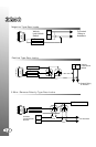
Starter
Heater
Power
Ignition 1
Jumper Selectable
Power
Note: The antenna must be connected before the system will operate.