


Installation Guide
Installation Guide
1350 Wiring Diagram Page 3
Pre-Installation Page 4
Components
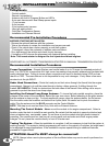
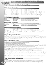
Pre Installation Check
Installation Procedures
Wire Connectors Page 5
6 Pin Connector
11 Pin Connector
5 Pin Connector
4 Pin Connector
Jumper Positions
Installation Page 6
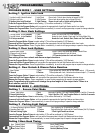
Basic Installation - Quick start
Plug-In The Module
Auto Tach Learn
Programming Page 7-9
Program Overview & System Reset
Program Menu 1 (User Settings)
Program Menu 2 (Additional Settings)
Program Menu 3 (Starter Settings)
Program Menu 4 (Tach Settings)
Operations Page 10
Single & Dual Car Operation
Timer Mode
Manual Transmission (Reservation Mode)
Additional Operations Page 11
1st & Second Car Transmitter Programming
Emergency System Service Mode
Battery Replacement
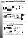
Relay Diagrams Page 12
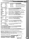
BLUE
GREEN
RED
RED
YELLOW
Green
Blue
Red
Door Lock
Door Unlock
Voltage Inverter Output
11
55
33
22
44
66
Starter
Heater
Power
Ignition 1
Jumper Selectable
Power
Factory Re-arm
(-) When Running/Armed
Factory Disarm
Trunk Release
(-) Horn Honk
Park Brake*
(+) Door Trigger*
(-) Door Trigger*
Park Lights
Hood Pin Switch
Ground
Brake Switch
Tach Detection
Glow Plug (Diesel)
(-) When Running
Input Trigger To Start
Sensor Ground Output
YELLOW
WHITE/BLUE
BLACK
BROWN
RED/WHITE
PURPLE
BLUE/WHITE
PINK
White/Violet
BLACK/WHITE
BLUE
WHITE
GREEN/WHITE
GREEN
ORANGE
3 PIN
RED
4 PIN
Blue
S
IDE VI
EW
ACTIVE RF ANTENNA**
WHITE
30amp Output
30amp Output
30amp Input
30amp Input
30amp Output
30amp Output
(-)500ma Output
(-) 500ma Output
(-) 500ma Output
(-)500ma Output
(-)500ma Output
(-)500ma Output
(-)500ma Output
Negative Input
Positive Input
Negative Input
Negative Output
Negative Output
(+ or -) Input
Negative Input
Negative Input
Positive Input
Positive Output
A/C Input
Negative Input
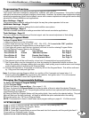
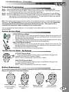
Access To
Jumpers
1 2
3
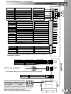
The jumpers control the output from the white wire
from the six pin harness. Place the jumpers in the
following order to change the output.
Note: The default setting is second ignition.
Output on White wire Jumper position
Second Starter Position 1
Second Accessory Position 2
Second Ignition Position 3
Status Led’s
Program Button
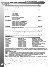
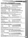
TABLE OF CONTENTS
WIRING DIAGRAM
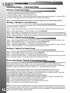
If the remote starter has a failed start attempt or if a safety input is activated the Diagnostic Memory will
store up to four shutdowns in memory. This information can then be accessed to determine the source of
the shutdown.
To Enter Diagnostic Mode:
Step 1 - Turn the ignition on wait two seconds then turn off. Press the Program Button and release.
Step 2 - The system will respond with three park light flashes and the horn will honk (optional) the
same number of times as the events in memory. ( Maximum four events, four honks)
NOTE: If the horn does not honk, there are no events in memory.
Step 3 - Press the Program Button once to view the last shut down code. The (optional) Horn willhonk
once to confirm code one. (If the horn does not honk, there are no codes in memory).
Step 4 - The LED’s on the antenna will flash a code corresponding to a shut down trigger. Press the
Program Button again to check the second code. The horn will honk twice to confirm code two.
Step 5 - To Clear Diagnostic Memory. While in Diagnostic Mode press and hold the Program Button for
five seconds. The park lights will flash and the horn(optional) will honk once.
NOTE: Once diagnostic memory has 4 shutdown events in memory, the system will not record any
further shutdown events until the system memory has been cleared.
DIAGNOSTICS
2
3
* These connection’s are only necessary for installation’s on manual
transmission vehicles.
**The antenna Must be connected for the system to operate
Jumpers
PARK LIGHTS STATUS LED DIAGNOSTIC CODE
3 Flashes Series of 3 Flashes Door Opened “M” Models
3 Slow Flashes LED’s On Solid System Is In Service Mode
4 Slow Flashes Series of 4 Flashes Not in Reservation Mode “M” units
5 Flashes Series of 5 Flashes Hood Pin Opened
5 Slow Flashes Series of 5 Flashes Ignition On During Start Attempt
6 Flashes Series of 6 Flashes Brake Pedal Shutdown
7 Flashes Series of 7 Flashes Tach Lock-Out
8 Flashes Series of 8 Flashes 3 Start Attempts with no start