


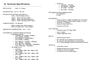
CON 1: Cable Description and Colors
PIN
No.
Cable Description Color
1 Optional (free) Black/White
2 Optional (free) Red/White
3 Optional (free) Red
4 (free) Black
5 (assigned) Microphone Input (HF+) Purple
6 Connect to Alarm Siren (COMM) Blue/White
7 Connect to Alarm Siren (NO) Blue
8 (assigned)Microphone to Ground (GND) Purple/White
9 (assigned) Headset Speakers (HF+) Green
10 (assigned) Headset Speakers (HF-) Green/White
CON 2: Cable Description and Colors
PIN
No.
Cable Description Color
1 +12V Battery Power Input (+) Red
2 Power Ground (GND) Black
3 Connect to SOS Emergency Button (+) Blue
4 Arm Switch (from existing Car Alarm) Brown
5 Disarm Switch (from existing CarAlarm) Brown/White
6 Connect to Interior Light (if no delay timer) Purple
7 ACC (+12V) Yellow
8 Immobilizer Relay (+) White
9 Door Unlock (NO) Purple/White
10 Door Unlock (COMM) Grey
11 Door Unlock (NC) Black/White
12 Door Lock (NO) Red/White
13 Door Lock (COMM) Green/White
14 Door Lock (NC) Green
10
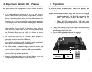
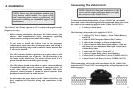
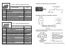
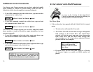
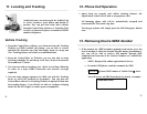
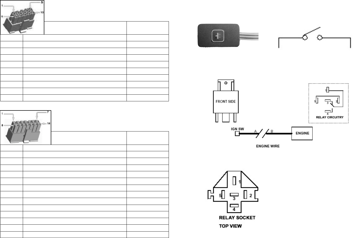
Installation of SOS Emergency Push Button
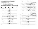
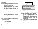
Installation of Relay for Immobilizer function:
To apply the Engine Enable/ Disable Relay, connect the following
cables from the relay socket:
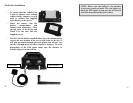
Plug the Relay into the Relay Socket to connect.
11
SOS Push Button
CON 2/ PIN 3
12 V
1. Black: Connect to one end
of Ignition line (A)
2. White: Connect to Vehicle
Unit, CON 1; PIN8 (White)
3. Middle: Connect to engine
end of ignition line (B)
4. Free
5. Yellow: Connect to ACC