


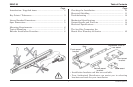

Use this information to plan your Linear Encoder installation.
• Understand your mounting requirements.
• Follow kit instructions when using an Acu-Rite Companies
Inc. bracket kit.
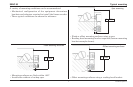
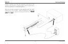
• Mount encoders close to ways to insure system accuracy.
• Mount with lip seals down and away from the work area.
• Brackets should be short and rigid.
• Surfaces must be in good condition, clean and free of
dirt and paint.
•
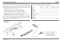
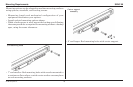
Do not remove shipping brackets until instructed. Do not remove shipping brackets until instructed.
Do not remove shipping brackets until instructed. Do not remove shipping brackets until instructed.
Do not remove shipping brackets until instructed.
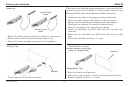
• Shipping bracket spacers can be used to insure .059” gap.
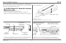
• Mount from either side to obtain desired cable exit direction.
• Tolerances of .005” TIR apply to all mounting dimensions.
•
Center support surface required for all measuringCenter support surface required for all measuring
Center support surface required for all measuringCenter support surface required for all measuring
Center support surface required for all measuring
lengths when not using a back up spar.lengths when not using a back up spar.
lengths when not using a back up spar.lengths when not using a back up spar.
lengths when not using a back up spar.
• Limit equipment travel to less than measuring length.• Allow clearance for shipping bracket removal.
3 Acu-Rite Companies Inc.
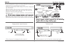
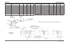
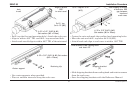
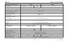
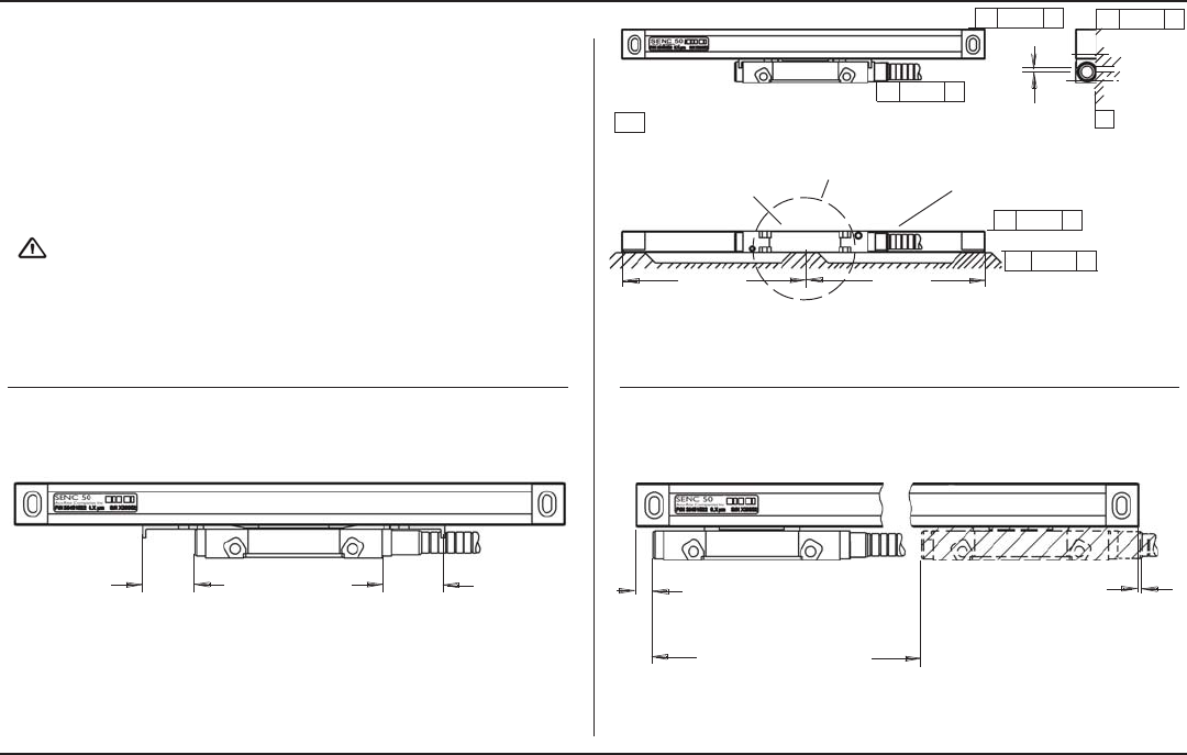
SENC 50 Key Points / Tolerances
Shipping bracket removal clearance
Reading head
assembly
Scale assembly
Gap
.059 ±.005”
[1.50]
B
-A- = Machine travel
Center support surface
required
Equal
Equal
//
.005 A
Total head travel
//
.005 A
//
.005 A
//
.005 B
//
.005 A
.26 [6.6]
Min.
Measuring length + 1”
[25.4] over travel
.037 [.9]
Min.
Slide brackets away
from the reading head
1.00
1.00