


Electrical Connections
Speedometer Wire Colour Purpose
Red/Black Ignition – a circuit which has 12V when the ignition is switched on AND
also connect to the Red wire of the Speedo reader
Red 12V – permanent power supply
Black/Green LED Indicator number 2 – switches to ground/earth/0V
White LED Indicator number 3 – switches to 12V
Black Ground/earth AND
also connect to the Green wire of the Speedo reader
Blue LED Indicator number 5 – switches to 12V
Yellow Speedometer signal – connect to the BLUE wire of the Speedo head reader
Blue/Black LED Indicator number 4 – switches to ground/earth/0V
Green LED Indicator number 1 – switches to 12V
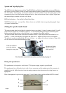
NOTE! If you are using one 12V switched for both the left and right m/c indicator lights you will need to
fit two diodes in the circuit thus;
Diodes are available from Acumen Electronics
Free of Charge on Request – or from any
Electronics stockist.
M/c Ind Light
M/c Ind Light
Speedo
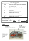
Using it
Knowing the controls
INC button
MOD Button
As the name suggests;
The MODE Button –
It increases values of the Trip
This changes from ODO to TRIP to CLOCK
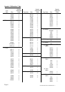
and also sets the speedometer ratio
or Clock or Speedo ratio
DEC button
As the name
suggests;
It decreases
values of the
Trip or Clock or
Speedo ratio
UNIT button
As the name suggests;
It changes the Speedo,
trip and ODO from
Miles to Kilometers and
vice/versa
Page 4