


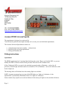

Speedo and Trip display filter
The LED’s for the Speedometer and the Trip/ODO/Clock are Red in the standard version and White in
the Special Version. Either version will need some filtration added to enhance the contrast and, therefore,
the ‘viewability’ of the display. Acumen has included a selection of filters in the kit for this purpose. We
recommend you try the filters before adding the fascia – then cut the chosen filter to slightly larger than
the chosen display window and stick to the fascia.
RED Led indication. – Use the Red or Dark Grey filters
WHITE Led indication – use any filter. Other colours are available from most good photographic shops
or contact Acumen direct.
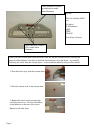
Fitting the speedo reader head
The speedo reader head can be fitted to either the front or rear wheel – it doesn’t matter which. You will
need to fit the magnet into a suitable receptacle – we recommend fitting the magnet within the plastic
holder and put the plastic into a disc bolt head – us a ‘superglue’ for added security.
The speedo reader head mounts inside the self-adhesive block. Adjust the position of the head so it is
within 5 – 15 mm of the magnet, and tighten the grub screw – nipped-up only! Do not over-tighten.
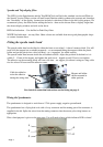
The adhesive on the mounting block will cure over time – we suggest you mount it using two long cable
ties for at least 24 hours until the adhesive cures.
Cable ties added to
assist the adhesive
during the curing time
Magnet and holder
shown mounted in
either position.
For electrical connection instructions see the listing on page 4.
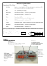
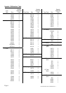
Wiring the Speedometer
The speedometer is designed to work from a 12Vdc power supply, negative ground/earth.
The speedometer has a flying lead on it with a 9-way connector and the mating part of the connector is
supplied in the kit. Splice the wires from the mating connector into the motorcycle wiring harness as
appropriate.
Wire colour/purpose is given on the next page. You will need to know which indicator LED is where!
1
4
2
5
3
Page 3