25
Control Word Bit Descriptions
for Coast Stop
Network
Drive
Control
Input
(continued)
Precedence of the stop commands is:
1. Coast stop
2. Quick stop
3. DC brake stop
4. Ramp (Normal) stop
Coast stop
The drive output stops immediately and the
motor coasts to a stop.
• Drive display show UN.READY (unit
ready) when coast stop is active.
• Drive cannot run in any mode.
• Parameter 503, Coasting stop,
determines interaction with input 27.
NOTE
Drive always stops and ignores
serial bus commands to run when
OFF/STOP function is activated
from drive keypad.
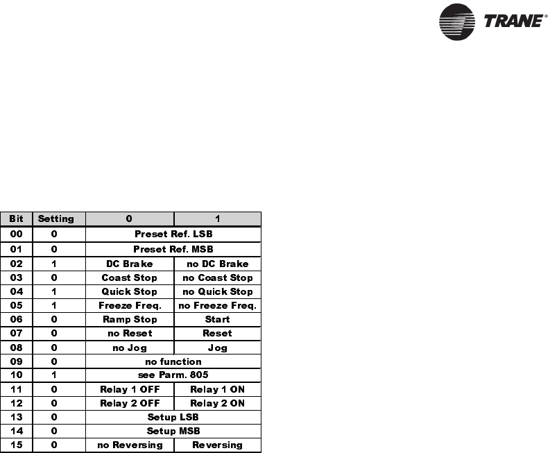
Control Word
The input network variable nviControlWord is
a 16-bit word that provides additional
operational control of the drive, as listed in the
table below. The settings shown represent the
Coast Stop command. The Control Word is
not supported by Tracer Summit.
Quick stop
The drive output frequency ramps down to
0 Hz according to time set in parameter 207,
Ramp Down Time.
• Drive display shows STOP.
• Drive cannot run in AUTO mode but can
run in HAND mode.
DC brake stop
The drive brakes the motor to a stop using DC
injection braking.
• Parameters 114 and 115 determine
amount and time of DC current applied
for braking.
• Drive display shows DC STOP.
• Drive cannot run in AUTO mode but can
run in HAND mode.
• Parameter 504, DC Brake, determines
interaction with inputs 19/27.
Ramp stop
The drive output frequency ramps down to
0 Hz according to time set in parameter 207,
Ramp Down Time.
• Factory setting is 60 sec for fan
applications and 10 sec for pump
applications.
• Drive display shows STAND BY.
• Drive can run in HAND mode or AUTO
through a digital input command.
• Parameter 505, Start, determines
interaction with input 18.


