Chapter 2 Location and Function of
Parts and Controls
2-12
Chapter 2 Location and Function of Parts and Controls
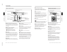
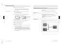
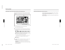
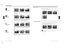
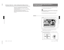
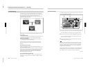
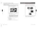
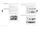
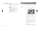
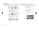
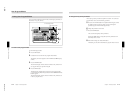
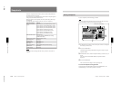
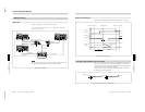
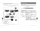
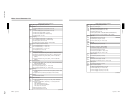
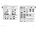
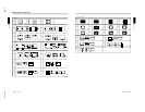
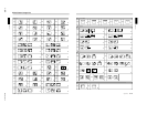
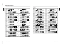
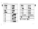
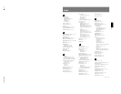
4 HOLD INPUT button
To hold the primary cross-point bus settings and the
auxiliary bus settings (signal selections) fixed when
recalling a snapshot, press this button. When you press
this button, it lights, and when you recall a snapshot,
the system is in the hold input mode. When you recall
a snapshot in this mode, all settings are recreated on
the control panel except those relating to the primary
cross-point bus and the auxiliary bus.
Press the button once more to turn it off and exit the
hold input mode.
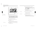
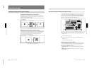
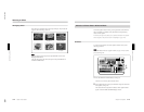
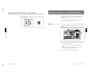
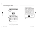
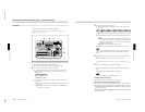
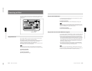
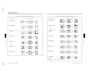
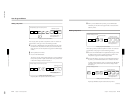
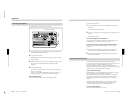
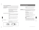
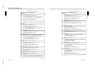
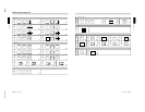
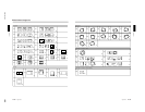
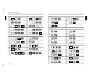
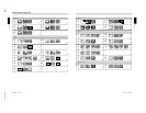
qa Location section
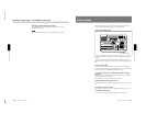
1 LOCATION button
Press this button to use the joystick and Z-knob. When
you press this button, it lights, and enables the joystick
and Z-knob.
Press the button once more to disable the joystick and
Z-knob, and return the effect pattern to its default
position.
Holding down the INITIAL button while pressing this
button returns the setting to its default value.
2 Joystick
Use the joystick to position the effect pattern in the x-
and y-directions.
3 Z-knob
Turn the Z-knob to move an effect pattern in the depth
direction (the z-axis). With this you can change the
effective size of the pattern.
Chapter 2 Location and Function of
Parts and Controls
Chapter 2 Location and Function of Parts and Controls
2-13
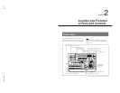
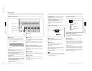
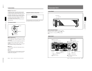
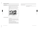
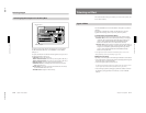
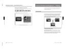
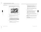
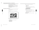
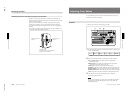
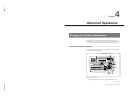
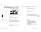
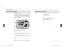
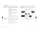
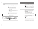
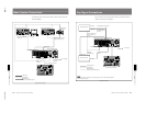
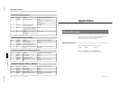
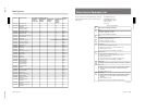
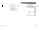
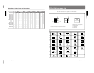
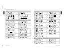
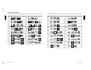
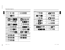
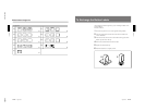
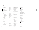
Processor Unit
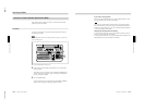
Front Panel
Power indicator
Power switch
Power switch and indicator
This powers the unit on and off. Press the “
” side of
the switch to power on, and the “
” side to power off.
When the power is on, the power indicator lights
amber.
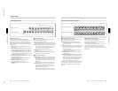
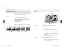
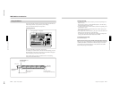
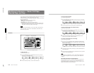
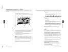
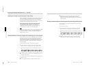
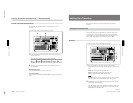
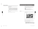
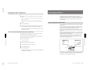
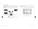
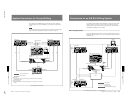
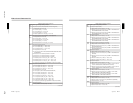
Rear Panel
1 PGM OUT connectors