starter will actuate. If difficulty is experienced in moving
the shift lever through the neutral position, raise the
switch until the shift lever
moves
easily. Place a film of
grease on the end of the safety interlock to reduce friction
and wear.
VARIABLE SAFETY INTERLOCK
FIGURE 21
Power Take-Off Clutch and Belt Stops: The power take-off
clutch can be correctly adjusted only when the attachment
such
as
a mower or sickle bar is mounted and the drive belt
connected. The clutch adjustment is made by moving the
set collar located
behind the left footr&. Loosen the set-
screw on the collar and adjust it so there is about
l/4”
clearance between the
colla
and the end of the rod guide
when the clutch is engaged. BE SURE, THE SPRING TEN-
SION LEVER AT’TtiE LEFT REAR OF THE TRACTOR
IS PULLED BACK IN THE TIGHTENED POSITION. Set
the clutch only tight enough to drive the attachment with-
out belt slippage. Unnecessary belt tension will cause rapid
wear of the belt and pulleys. See figure 22.
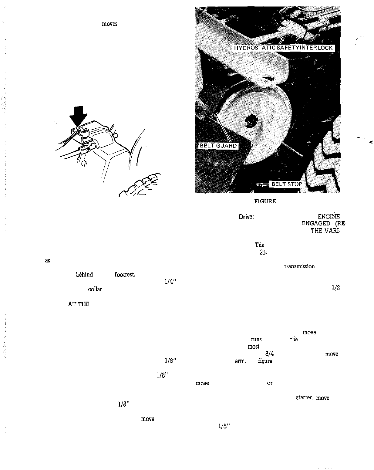
The power take-off belt stop should be adjusted after the
clutch has been adjusted and with the attachment. Loosen
the mounting bolt and adjust the belt stop so it is
l/8”
from the belt when the clutch is engaged. See figure 22.
Tighten the mounting bolt securely and check the
l/8”
di-
mension again.
The belt guard located at the top of the power take-off un-
it should be adjusted so there is
l/8”
clearance between
the guard and the belt when the power take-off clutch is
engaged. Loosen the mounting bolt and
move
the belt
guard as required. See figure 22. Tighten the mounting
bolt securely.
12
,FIGURE
22
Variable Speed
D&e:
ALWAYS HAVE’THE
ENGI:&E
RUNNING
AND THE CLUTCH ENGAGED.‘(RE-
LEASED) WHEN ATTEMPTING TO MOVE THE,VARI-
ABLE SPEED CONTROL LEVER. Adjust the variable
speed drive as follows.
The
reference numbers correspond
to the numbers on figure
23;
1. With the engine running and the transmi&ion in neutral
place the variable control in the fast (7) position.
2. Remove the spark plug wire and place it at least
.1/Z
inch away from the spark plug.
3. Loosen slightly, the bolt which holds the control arm to
the variable lever.
4. Rotate the engine with the starter and
move
the vari-
able arm until the belt runs flush with tlie top of the small
pulleys. This may be
most
easily done by using a bar about
2 to 3 feet long and about
314
inch in diameter to
move
the flat variable
arm.
See
figure
23.
5. Tighten the bolt loosened in step 3, being careful not to
move
either the control lever or the variable arm.
”
6. While rotating the engine with the
Starter,
move
the
control lever to the slow (1) position. Loosen the lock nut
at the tumbuckle and alternately adjust the turnbuckle
and rotate the engine. Adjust the turnbuckle so the belt
will ride
l/8”
below the top of the large pulley when the
engine is rotated.


