:.:
.:,
;.:7
..~..
.~::
FIGURE 3
ATE THE LIGHTS FOR OVER 10 MINUTES WHEN
THE GENERATOR LIGHT IS ON OR THE BATTERY
MAY DISCHARGE ENOUGH SO IT WILL NOT START
THE ENGINE.
6. Fuel Gauge and Filler Cap: The gauge measures the level
of fuel in the tank. Turn the cap counterclockwise to re-
move for adding gasoline.
7. Hourmeter IOptional): The hourmeter is used to record
the number of hours the engine runs, though it will oper-
ate any time the ignition switch is ON even if the engine
isn’t running.
FIGURE 4
8. Power Take-Off Control Lever: The power takeoff lever
controls power to attachments such as a mower
or
sickle
bar which are driven by the center power take-off unit.
Pull the lever up and forward until it snaps
over center
to
engage the P.T.O. Pull it back and down to disengage. The
tractor engine should be running at 112 to full engine
speed when the power take-off is engaged to absorb the
initial effort of the added load. ALWAYS DISENGAGE
THE P.T.O. AND WAIT UNTIL ALL ATTACHMENTS
HAVE STOPPED MOVING BEFORE LEAVING THE
TRACTOR SEAT.
FIGURE
5
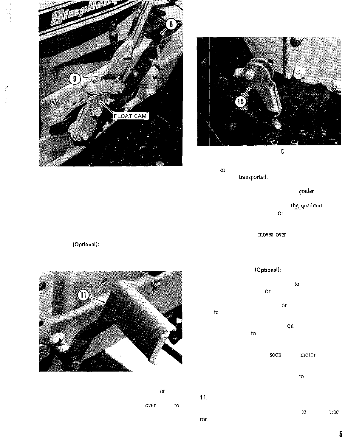
9. Lift Lever: The lift lever is used for lifting the rotary
mower
,or
other attachments out of the operating position
so they can he
transport.ed.
By using the notches and pin
holes provided in the quadrant, you can regulate the op-
erating height of attachments such as the grader blades and
snow throwers. The thumb button on top of the handle is
pressed to disengage the latch from
thequadrant so the
lever can be moved forward or back as required and
locked in position. Placing the float cam in the “UP” po-
sition will allow the lift lever to “float” through any posi-
tion as an attachment
moves
over rough surfaces. SEE
THE ATTACHMENT BOOK FOR SPECIFIC INFORMA-
TION ON HOW THE LIFT LEVER SHOULD BE USED
WITH YOUR ATTACHMENTS.
10. Power Lift Switch (Optionall: The Power Lift Switch
controls the electrically operated power lift unit. Push the
toggle switch forward when you wish
to
raise a center or
rear mounted attachment
or lower a front mounted at-
tachment. Pull it back toward you to raise a front mount-
ed attachment or lower a center
or
rear mounted attach-
ment
to
the operating position. The power lift will immed-
iately stop and hold in any position when you release the
toggle switch. The height indicator qn the left side of the
tractor can be used
to determine what position the lift is
in. The lift motor will ratchet when it has reached the end
of its travel. It is not harmful to the unit, but you should
release the toggle switch as
soon
as the motor begins to
ratchet to prevent unnecessary wear. If the motor is al-
lowed to ratchet for an extended period of time, a circuit
breaker will open disconnecting power
to
the lift motor.
It will automatically reset itself after a few minutes.
11.
Clutch and Brake Pedal: Depressing the pedal will first
disengage the tractor drive clutch. As you continue to de-
press the pedal the brakes will be applied
to
stop the trae
for.
CAUTION: ON HYDROSTATIC TRACTORS THE
5


