OPM_GTU_TWR_1K0_3K0_XUS_V015 15 DE GT Series: User manual rev date 8-11-04
Digital Energy
4.2 RS232
The RS-232 communication port provides the following functions:
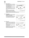
1 - Monitoring charger status
2 - Monitoring battery status and condition
3 - Monitoring inverter status
4 - Monitoring UPS status
5 - Monitoring the AC utility power status
6 - Turn on/off UPS on schedule for power saving
7 - Adjust transfer voltage
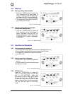
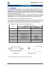
Pin Assignment:
Pin 2 : PC receives line RS-232 data from UPS.
Pin 3 : PC transmits line RS-232 data to UPS.
Pin 5 : Signal ground.
Pin 4,6,7 : Reserved for plug and play function.
The UPS data is provided at 2400 bps baud rate and made up of 8-bit, 1 stop-bit and no parity
bit. All information is encoded in ASCII format.
Hardware:
Baud rate 2400 bps
Data length 8 bits
Stop bit 1 bit
Parity none
Cabling:
Standard sub-D 9 cable (UPS side: male, PC side: female)
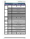
4.3 Dry Contact
Its major functions are some or all of the following:
1 - to broadcast a warning when the AC utility power fails.
2 - to save open files before the battery is exhausted.
3 - to turn off the UPS via computer(s).
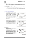
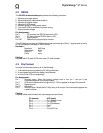
Pin Assignment:
Pin 1 : Normally open. When the battery voltage level is low, pin 1 and pin 5 are
connected together via a photo coupler.
Pin 3 : UPS will shut down when a high level (5~12V) is applied for at least 3.8 seconds.
Pin 5 : Signal ground.
Pin 6,7 : Reserved.
Pin 8 : Normally open. When the AC utility fails, pin 8 and pin 5 are connected together via
a photo coupler.
Cabling:
A special cable must be used with a pin assignment as follows:
PC (female) UPS (male)
Pin 1 -----------------------Pin 1 (Battery Low)
Pin 3 -----------------------Pin 5 (GND)
Pin 4 -----------------------Pin 3 (Shutdown)
Pin 7 -----------------------Pin 6
Pin 7 -----------------------Pin 7
Pin 8 -----------------------Pin 8 (AC Fail)